
I am using a W8JK 2 elements beam antenna feed with a ladder line or 450 Ohms twin lead. The antenna is working from 14Mhz up to 50Mhz .
Previously i was using a Mac Coy ATU which is is providing great results but unfortunately before moving to Brunei Darussalam , i gave the ATU to a good friend since i was not planning to use the W8JK antenna here.
For different reasons i need to bring back the W8JK antenna a i need for this purpose a good balanced Antenna tuner.
During my initial test I was using a standard ATU using a 4:1 Balun to feed the twin lead.
Unfortunately this solution is not relevant and immediately i have noticed the feedline was not well symmetrical implying an unbalanced antenna dowgrading the gain , directivity and radiation pattern.
Since i move to Brunei i have limited access to electronic components and i just bring here a roller inductor , 2 air variable capacitors (250pf) and misc. Not enough to build again a Mac Coy tuner.
Few days ago i find an interesting design from PA0FRI Fritz and had decided to buid the S-Match antenna tuner.
https://pa0fri.home.xs4all.nl/ATU/Smatch/smatcheng.htm

Fritz webpage is describing perfectely the build and i will skip details of my build since it will depend the arrangement you may choose.
Variant Design
I have basically 2 main constraints:
- I need to deal with only the components and hardware i have here.
- I need to ensure the ATU is able to tune very low impedance , means about 3 Ohms (On 14Mhz , the W8JK antenna has about 3 to 4 Ohms impedance only.
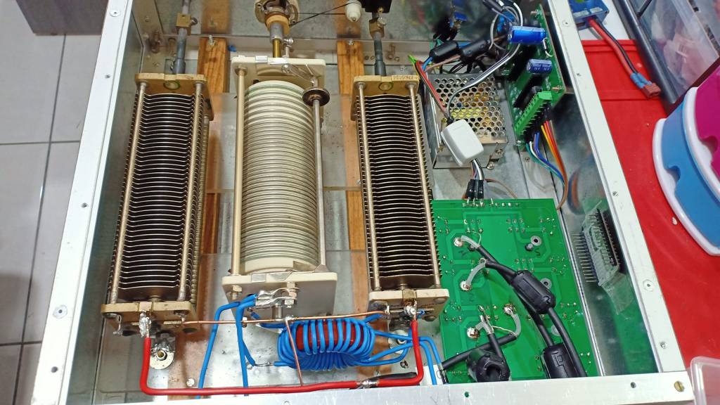
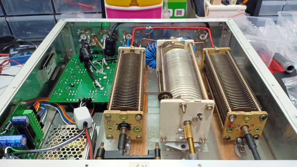
After many lab tests and scratching my head i manage to achieve a great design which is a variant from PA0FRI original design.

The good thing with this design you are using a T200 iron powder coil instead of stacked Air coils and a switch according the frequency and band . The tedious thing is you need to find yourself the correct value of the main coil and replicate it using the core . I was really tedious to achieve but the result worth the effort and time i have spent on it.
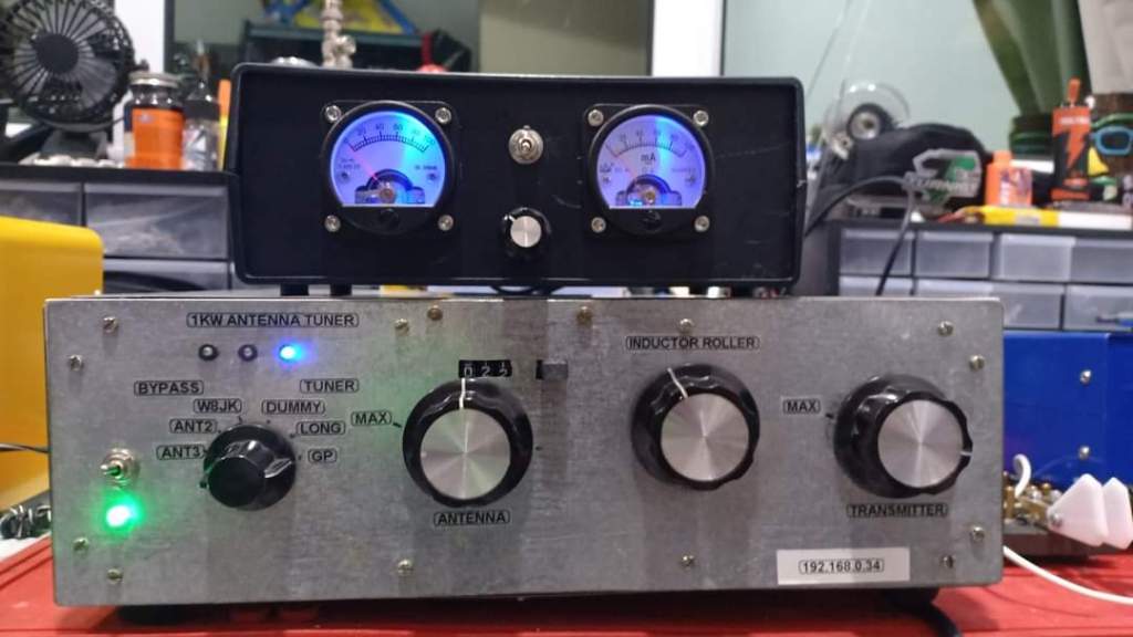
The addition of the switch for the capacitors is able to provide :
- More flexibility and tuning range.
- If any discrepency is noticed at the output using two vu-meters (Current Probe) monitoring the output to the twin-lead, you will be able to fine tune it and feed your antenna with a perfectely balanced input.
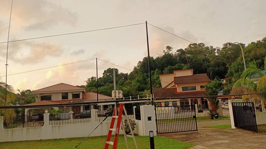
Since my antenna mast is not here yet , have plenty of time to fine tune my antenna and antenna tuner with some tests using t-match, z-match , Mac Coy variant and few others.
This ATU is also an antenna Switch controlled by a WebPage .
Last week end i checked the W8JK fed by a standard ATU but unfortunately the current and voltage feeding the antenna are totally unbalanced (test with my Grid Dip and RF field meter) . Previously in France i was using a Mac Coy Tuner but by design this tuner was hardly able to tune the W8JK on 14Mhz due to low impedance .
With the S-match ATU from PA0FRI, tuning the W8JK on 14Mhz and above is just piece of cake. The roller inductor is really great to balance efficiently both lines for the twin lead.
I am scratching my head and brain to add two amp meters to check the twin lead energy transfer and field in order to ensure they are perfectly balanced but unfortunately not space available on the front panel and there is a good chance i need to add and external circuit.
Now the energy transfer is far better and balanced which was not the case previously (not the end of the world using the previous system but loosing energy and efficiency is not my target).
This tuner should be able to handle about 400 to 500w
Measurements outcome
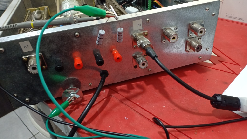
The unbalance/balance ATU is now equipped with low and high impedance output. Since the W8JK is mostly a low impedance antenna (very low on 14Mhz with about 3 ohm only) , the low impedance output will be used.
Later if needed i can use the high impedance output for Eg. Loop antenna feed with twin lead or ladder line . The lab measurements are providing two main outcomes:
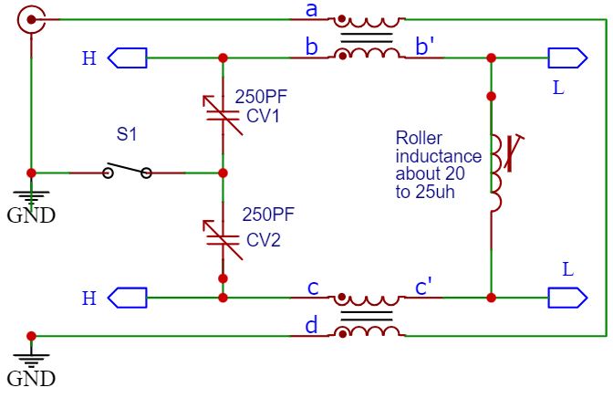
-the main circuit is in fact a resonant tank circuit and the tuning using the roller inductor is able to bring the dip to the resonant frequency. Using a Nano VNA is showing clearly the DIP moving when adjusting the Roller inductance.
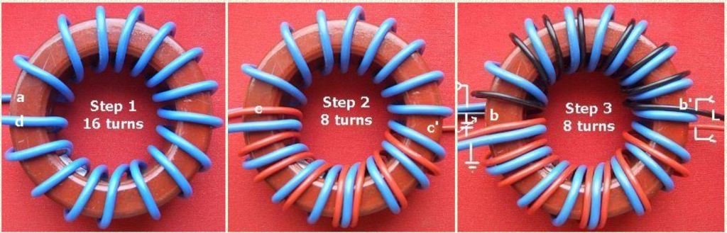
-The transformer using to iron powder coil with capacitors (14 to 16 turns for about 2.5 micro henry and 2 independent stacked couplers using 7 to 8 turns for each wires of the twin lead) are able to tune and adjust the match for the ladder line and load accordingly . The output to the 2 ladder wire is strictly identical regarding the level and with 180° out of phase which is the main target in order to provide a perfect balanced line (an unbalanced ladder line will affect the antenna radiation pattern , losses and discrepancies between the 4 monopoles). You will need to pay a particular attention during the winding of the Core and please note the winding direction for the 7 to 8 turns secondary winding (Black and red wires).
Some lab test using different load at the output from 2.6 Ohm for 14mhz up to 100 ohm for 50 mhz and the results were really good. No spurious dip and leakage strays at all and the tuning and dip are really sharp. Even my Mac Coy tuner was not able to achieve such results (false Dip).
Some tests prior the final build :


Nanovna test using different loads from 2.6 Ohms up to few hundreds (330 Ohms if i can recall).


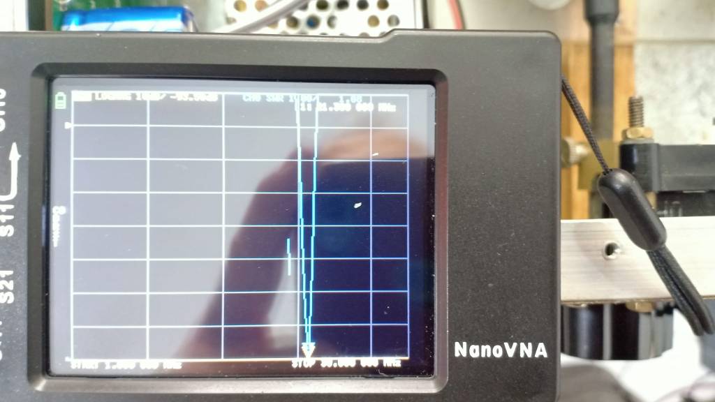

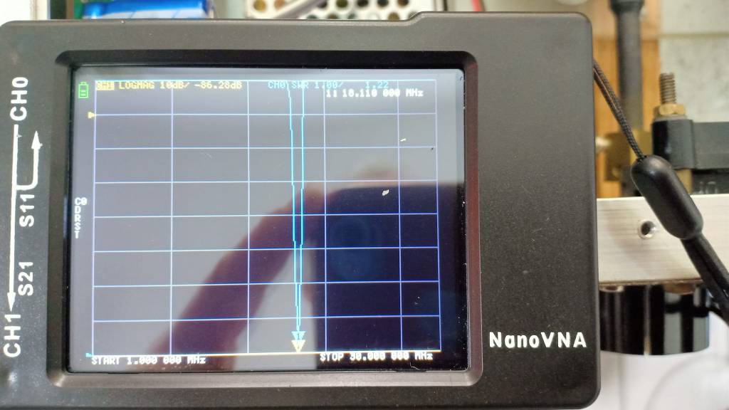
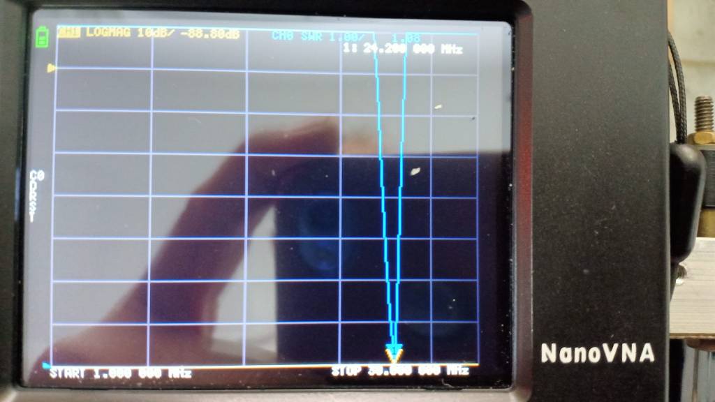
The lab tests are really great and the Dip is very accurate and sharp . you can notice no fake/false dip or spurious strays.
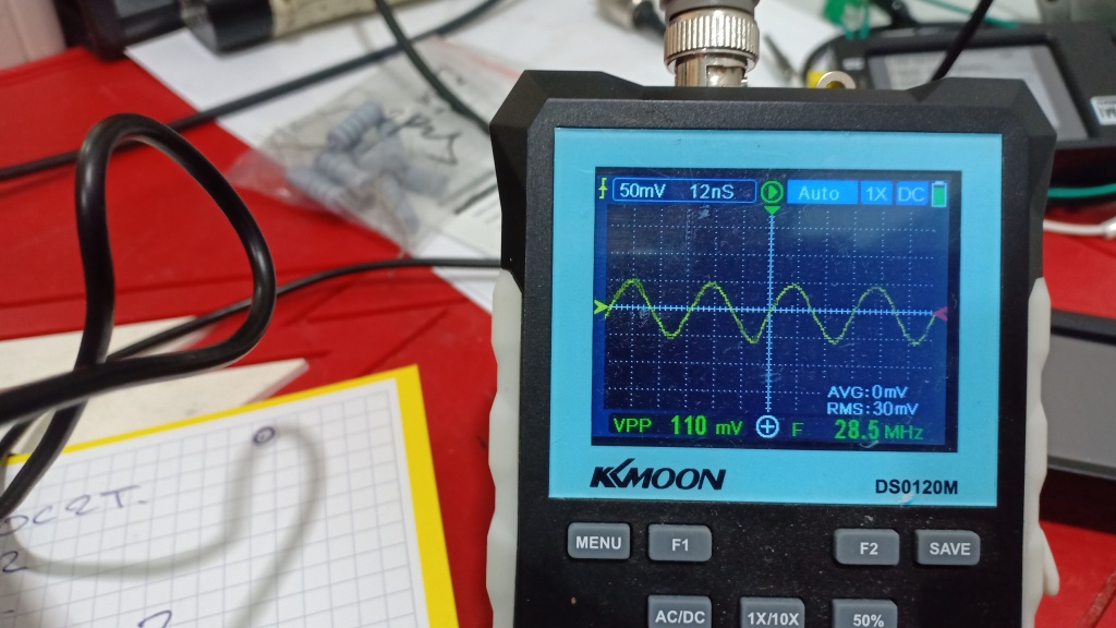
Output attenuation and balance check
The main goal is to achieve an ATU providing the the minimum attenuation when tuned .
In addition the output shall be balanced providing an identical output level with 180 out of phase which is very important.
Test conducted with a differential setup loaded with two 100 ohms non inductive resistors. the middle point is connected to the ground.

According the tests i had performed measuring the attenuation and the outout balance, i obtain really great results with only few minor insertion losses and the 2 capacitors are really assiting to provide a perfect balanced output
Input level:

Output level both wires

Simple check
A very simple test can be performed without any measurement tools using your receiver :
- Adjust your receiver to a good signal E.g. FT8 and report the receive level from your S-Meter. Obviously the ATU must be tune on the frequency you are using.
- The output has 2 plugs (A and B) feeding both wires of your twin-lead feeder.
- Disconnect one of the wire from the plug E.g. plug “A” and check the signal level on your receiver S-Meter with only one wire connected to plug ”B””
- Then disconnect the Wire from the plug “B” and connect it to the plug “A” –> if your tuner output is well balanced , you should have the same receive level.
- Repeat the same operation with the other wire from your twin lead feeder and ditto if the output is well balanced , the receive level should be identical whatever it is connected to both plugs. If this is not the case just apply a tiny adjustment on the capacitor or the roller inductor to achieve an identical level (This is why it is important to have a current probe monitoring the output of a symmetrical ATU).
- If you cannot achieve an identical level , you need to check the Core winding.
Life test on my W8JK antenna


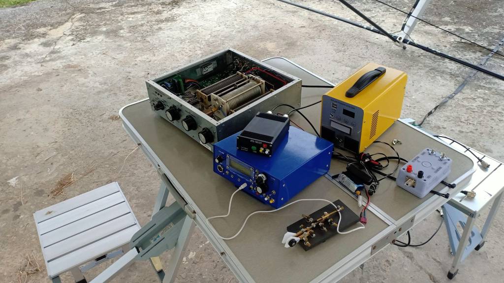
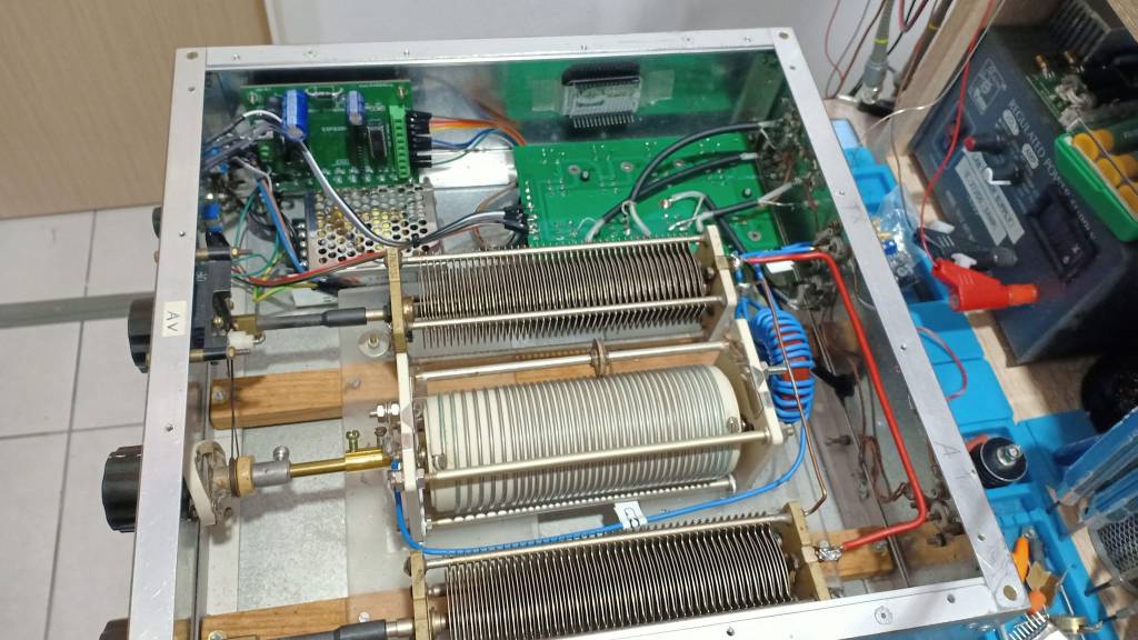
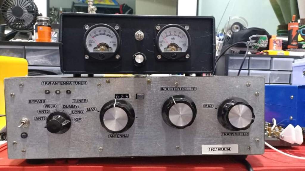
Final build
The BOM is :
- Two Variable Air capacitor 250pf
- One E.F Johnson Roller inductor 28uh (I bought the counter on EBAY many years ago)


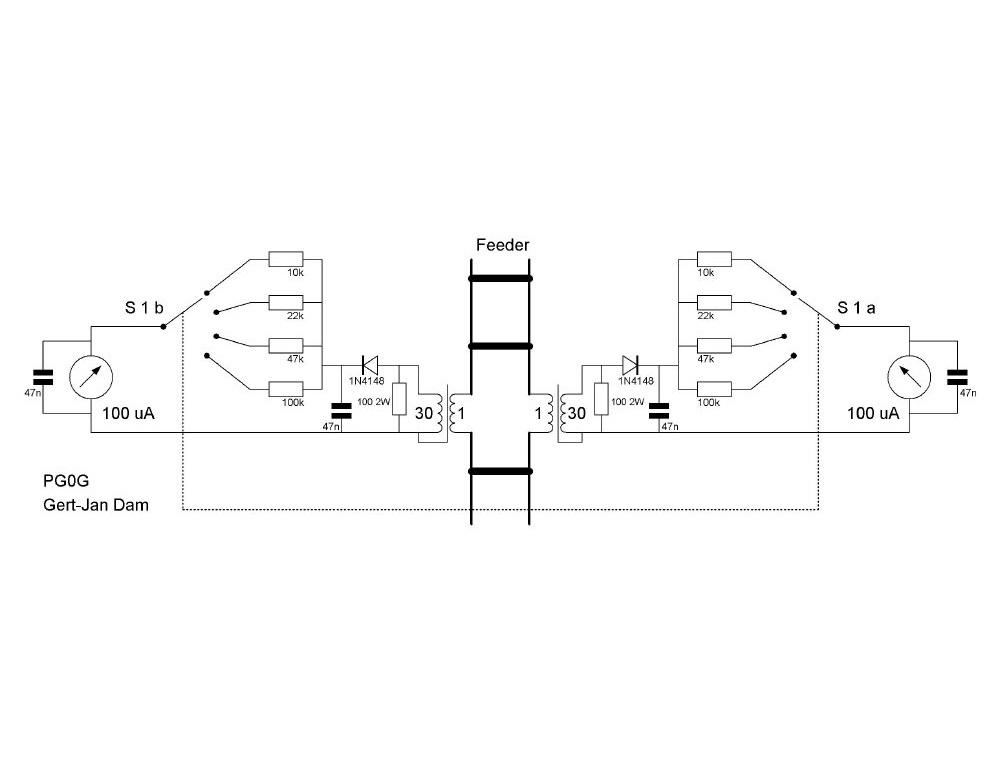
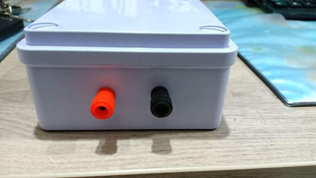
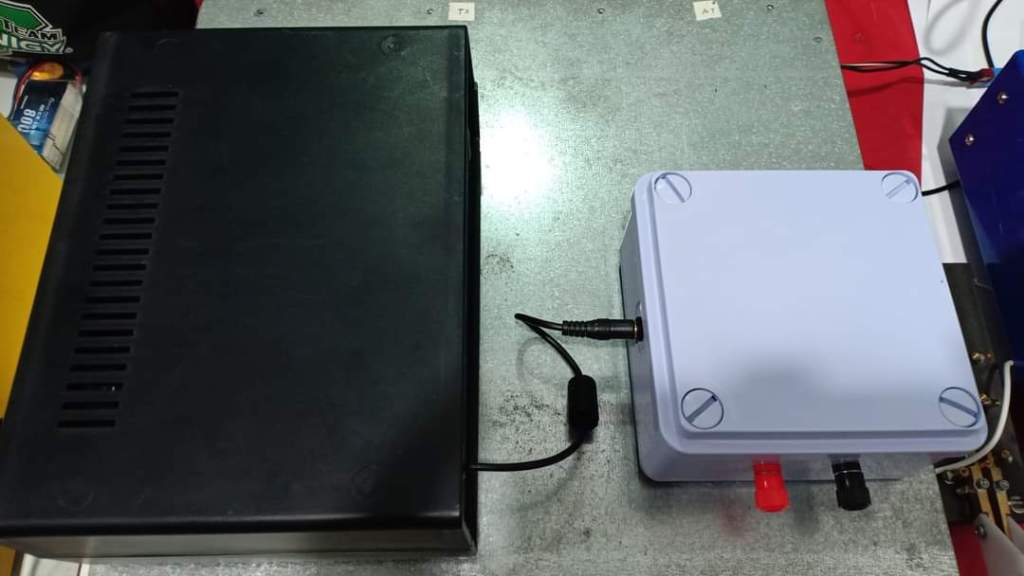
Inline current meter and probe
Adding a Current probe is really useful to monitor the current for each wire of the twin-lead to ensure everything is symmetrical.
You can find many design here :
http://www.qrz.lt/ly1o/LL%20tuner/default.htm
https://pa0fri.home.xs4all.nl/ATU/Ant%20current%20meter/Antenna%20current%20meter.htm
i am using a germanium diode BAT41 and be able to use a 100ma VU-meter with only 5w at the input. If you are using a 1N4148 you will need a 100ua VU-meter.
The core i am using is a T50-2.
You may need to adjust the switch resistors according the VU-METER and the Output power you are using.
I am using RG58 coaxial since my maximum output power is about 350w.


Conclusion
Easy peasy build and very efficient. The energy transfer at the output of the ATU is great and did not noticed any symmetrical discrepencies . The Switch addon will provide you the opportunity to perfectely adjust the output and ensure a strict balanced output to feed your twin lead.
Once more , building and testing this ATU was a great opportunity to tackle balanced transmission line to carry radio frequency (RF) signals.
Bear in mind twin lead or ladder lines are opposite in phase (180° out of phase) to the waves radiated by the other wire, so they superpose and cancel each other. This will imply to have a perfectely balanced ATU to ensure the both lines are strictely 180° out of phase to feed properly your antenna (In particular for the W8JK Antenna). It will prevent the twin lead to radiate and to provide nasty spurious.
Once more a big thanks to Fritz PA0FRI for this very nice design and sharing.
