
Homebrew uSDX SDR TRX
Introduction
This transceiver and variant you will find on internet is experimental and unfortunately by design and regarding the 8-bit ATMEGA328P limitation cannot meet minimun requirements regarding the regulation for SSB (Whatever the firmware you are using you or find on internet on different Facebook groups). With or without quad flipping , the IMD and SSB Bandwidth cannot meet the minimum FCC requirements. This design and variant is recommended for CW and Digital mode only!
The µSDX is a new open source, home brew multi band, multi mode QRP transceiver family that grew out of the QRP Labs QCX. Through some serious wizardry it retains an efficient “class E” RF amplifier for SSB and digital modes. It crams impressive SDR capabilities into an 8-bit ATMEGA328P.
you can find on this page an alterrnative design : https://f5npv.wordpress.com/usdx-sdr-1-02-custom-design/
The µSDX is not a product! It is is a family of developments using similar approaches. There are several design streams and often several versions of a design.
The µSDX Group is an open source development community. It is not a support group for a particular product. People participate because they enjoy not only developing projects but sharing what they have created. Unlike open source developments with a single leader, like Linux with Linus Tovalds, this effort has many people pursuing their own personal interests. People help because they are good people that like to nurture others.
All credits to :
* Manuel DL2MAN https://dl2man.de/
* Barb WB2CBA https://antrak.org.tr/blog/usdx-a-com…
* Guido PE1NNZ https://github.com/threeme3/QCX-SSB which were based on the
* QRP-Labs QCX by Hans G0UPL http://www.qrp-labs.com/qcxmini.html
One of my favorite forum : https://groups.io/g/ucx/topics
The project
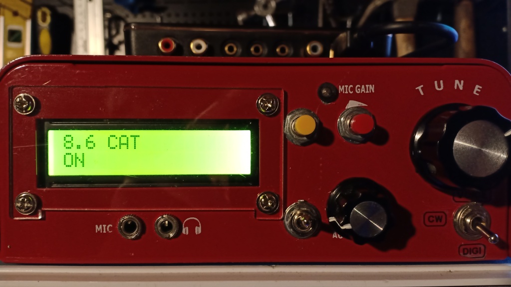
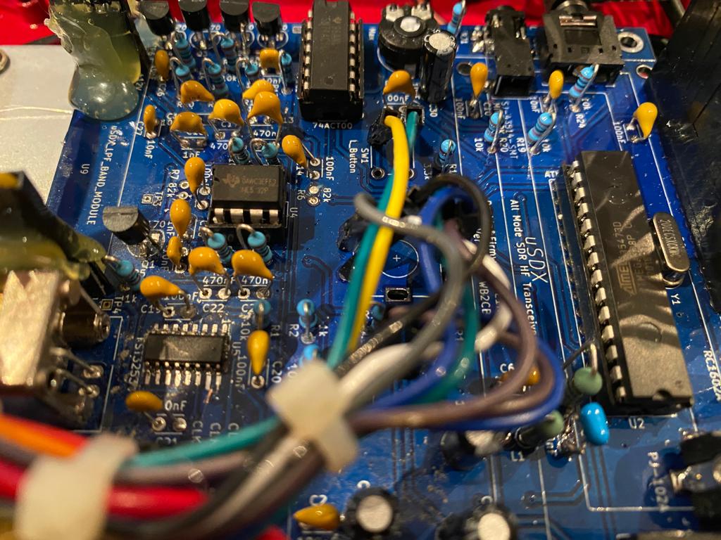
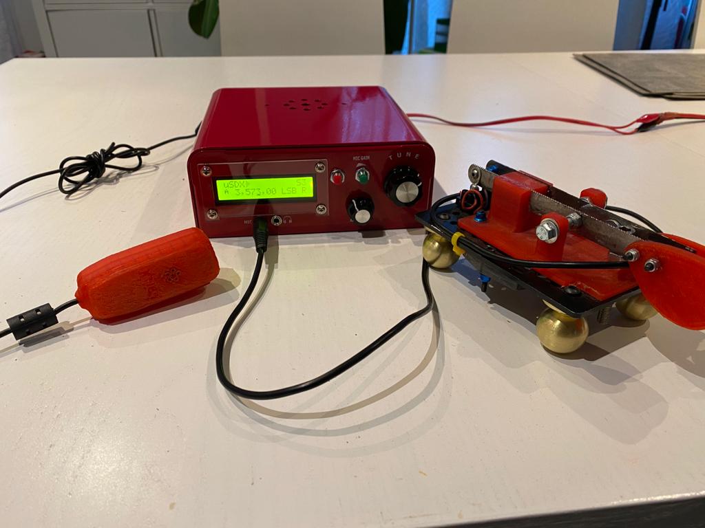
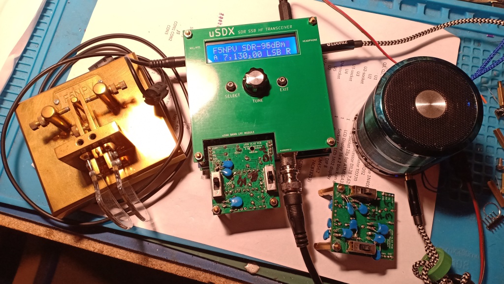
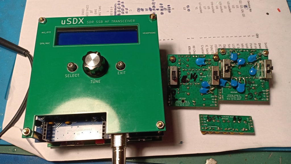
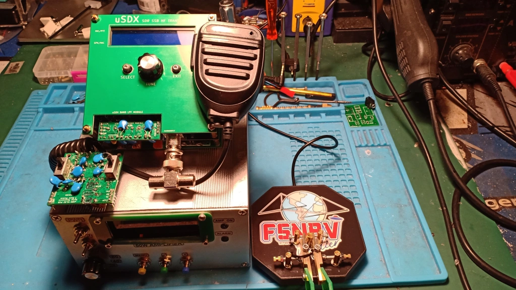
uSDX WB2CBA v1.02 PCB using 1.02X firmware . This is a triband (80,40 and 30/20m) version and the LPF is located on the side of the enclosure from Amateurradiokits (many thanks once more Sunil Lakhani for your great product)
I am not using Q5 and the output power is about 2 up to 3w . My bias setup is 10 and 90, drive setting is 3.
Receive and TX are great and surprisingly the modulation is not so bad (The LPF shoud be perfectly tuned in order to provide a good modulation . An out of shape LPF is providing a terrible modulation with a lot of IMD)
Last week-end i used this TRX during the French National CW contest and the rig was performing really well, the CW decoding was amazing.
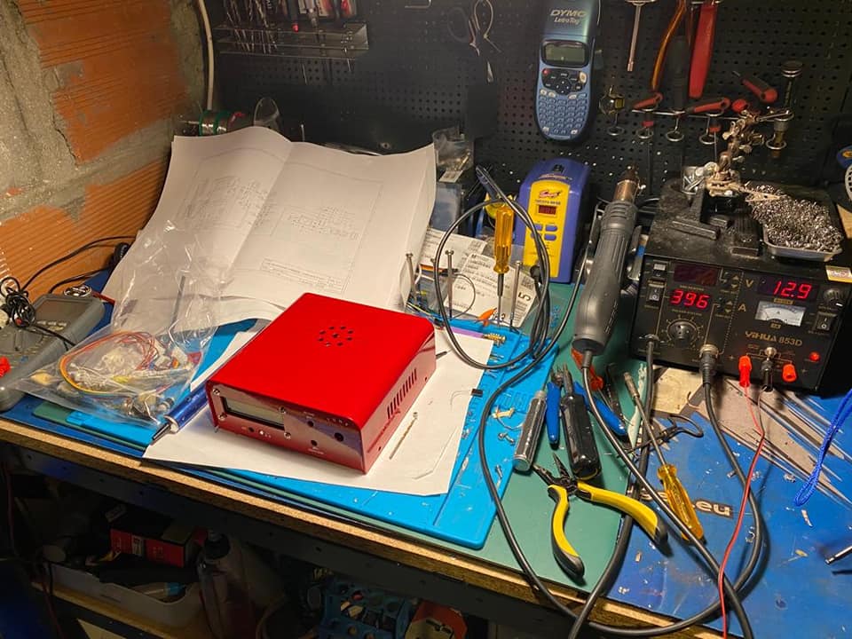
During the initial build i was using very cheap resistor and capacitor from my junk but the result was not acceptable with a high noise floor . I replace them with good quality components and the result was day and night compare to initial build .
Way-ahead: add a tiny radiator on the output transistor for a good cooling and using the pin 17 to control the external power amplifier (30/50watts).
So far so good a great TRX considering the size and the simplicity of the design and i use mostly this tiny transceiver FT8 and PSK31 modes. This transceiver is performing really well for digital modes.
ATMEGA 328P Sketch
You can download the original sketch from here :
https://github.com/threeme3/QCX-SSB/tree/feature-rx-improved
uSDX Firmware modification and enhancement
Currently the uSDX project is awaiting for the new hardware/firmware release from Guido (PE1NNZ) and Manuel (DL2MAN). The current enhanced firmware which is the 1.02w release will move to accomodate the new hardware. Currently i have built 3 uSDX and the forth one is on going . It will be my latest hardware release and all my uSDX TRX will use the current 1.02w firmware.
Guido has done a fantastic job regarding the firmware with significant enhancement since the release 1.02m. There is a good chance the current 1.02w release will not move a lot since the hardware is moving also. In order to accomodate my current hardware some intereresting features or enhancement are possible since the source is ready for modification.
For the past few days i have tested the following features and enhancement with modification on the 1.02w firmware :
https://drive.google.com/file/d/1dg_uG8WV5ib-WXTyx5uQHDW36V1MdwGo/view?usp=sharing
V11 release (the latest release from 02 Oct 2023 without mic att)
https://drive.google.com/file/d/1EuDkH7kE_IJHTcDubzOyNkIcYTLAwZHu/view?usp=sharing
An audio testing on TWENTE WEBSDR:
https://drive.google.com/file/d/1ukFoGu5Q8YbvllOvDLihyEzbfgKHF8PN/view?usp=sharing
Definitly the quality is far to be perfect but definitly better compare to some clone from Aliexpress or EBAY.
-CW tone level (CW Sidetone) :
With the 1.02w release the CW level is fix and cannot be modified with the front panel menu and i have added in the code a proposed modification in order to adjust from the menu the CW sidetone level which is really convinient.
TX QUADRATURE Swap : invert TX signal for phase changes > 180
Multi ADC : multiple ADC conversions for more sensitive (+12dB) microphone input
DIGI Mode ON/OFF:
This feature will provide optimization for digital modes: for super flat TX spectrum, (only down < 100Hz to cut-off DC components)
Microphone Gain:
Currently we cannot adjust the microphone Gain from the front panel and the current source code by default is activating the Microphone Gain. This feature cannot be modified from the front panel and i have added in the code a menu where you can activate or not the Mic Gain. This feature is really great according the Microphone your are using and in some case the gain should be activated or not. . In addition this modification can be used regarding the FT8 or some Digital modes according the interface or sound card you are using. The audio sweep and 2 tones test are providing quit good result . The IMD3 was better compare my current setup which using stock 1.02w Firmware. Some test with my local WEBSDR using a simple electret microphone not far from my location are providing better results compare to my initial setup and stock firmware.For FT8 and digital modes previously i cannot setup the transmit slot to frequencies above 2500hz due to some clipping and distortion . With this modification the AF slot can be setup to 2900hz without any issue .
MIC Attenuation:
By default the MIC attenuation is not activated. The step for the attenuation is 6db . Like the Mic Gain and according your microphone or interfaces you are using for Digital modes , it is quit useful to propose this feature to be activated from the Front panel. I add dedicated menu in order to activate or not this feature.This feature can work along with the MIC GAIN feature
The following sketch is adding steps adjustment you can adjust according your needs:
https://drive.google.com/file/d/1h0Hq09arVO_2rDH1r643cthwTDHbeuGT/view?usp=sharing
CW 600HZ/700HZ
I am still testing this feature because i have some side effect the the CW filters
Hereafter the New Menu features mapping with the Sketch (BOLT for the settings i am using SSB and digital modes):
-MICBOOST1 –> MORE_MIC_GAIN –> ON or OFF
-MICBOOST2 –> MULTI_ADC –> ON or OFF
-MIC ATT –> MIC_ATTEN –> ON or OFF
-DIGIMODE –> DIG_MODE –> ON or OFF
-MIC_DX –> QUAD –> ON or OFF
-TONE VOL to setup your CW Sidetone volume
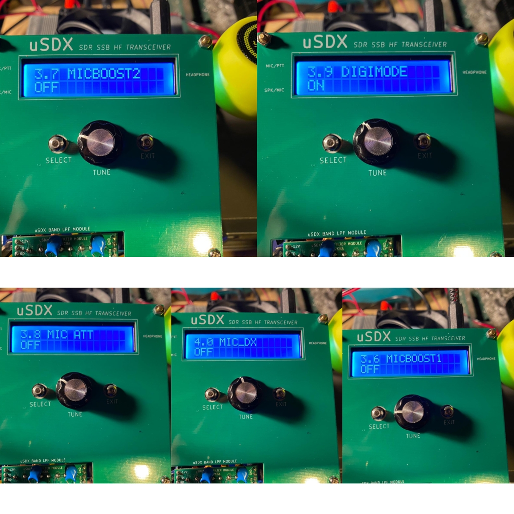
Obviously they are not tremendous changes on the firmware but some likely the MIC gain and the Mic Attenuator will assist to enhance your AF Audio quality during transmit in particular for SSB mode according the microphone you are using.
Obviously this kind of modification will not really assist if you have serious issue with SSB distortion , therefore it can really assist if you just some little distortion or clipping in SSB mode
In addition i add a feature for enabling or disabling the CAT Feature from the LCD Menu
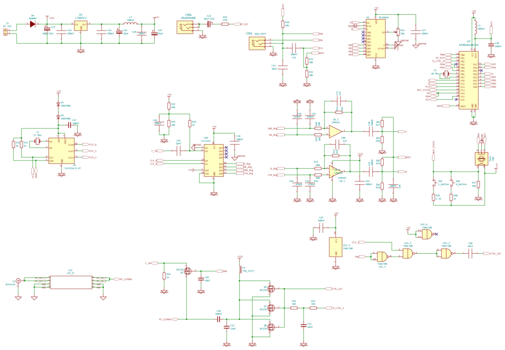
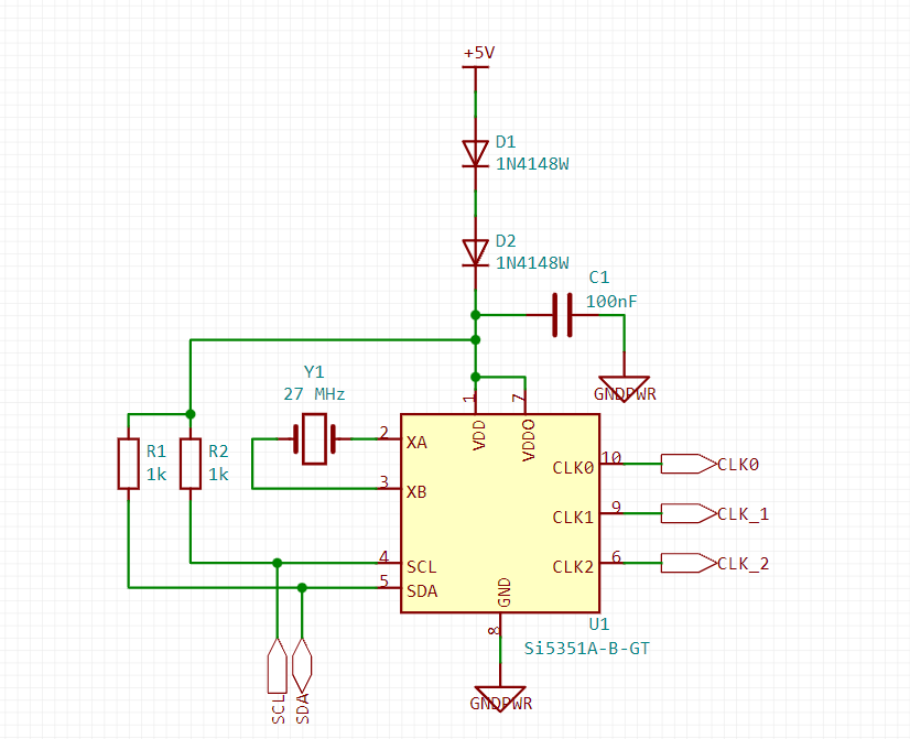
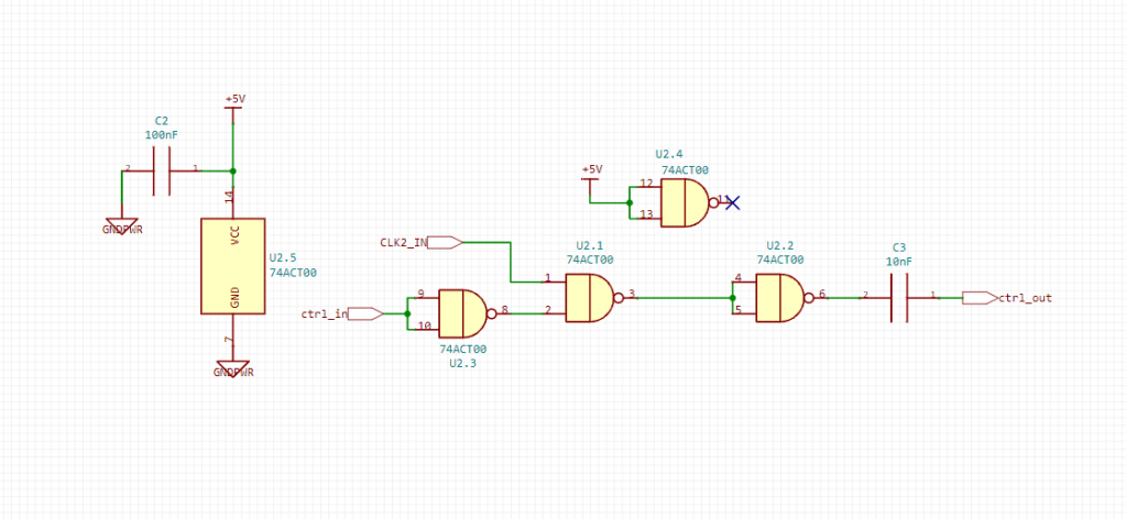
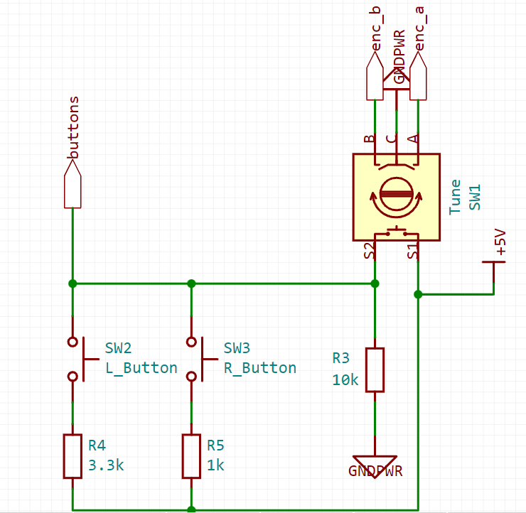
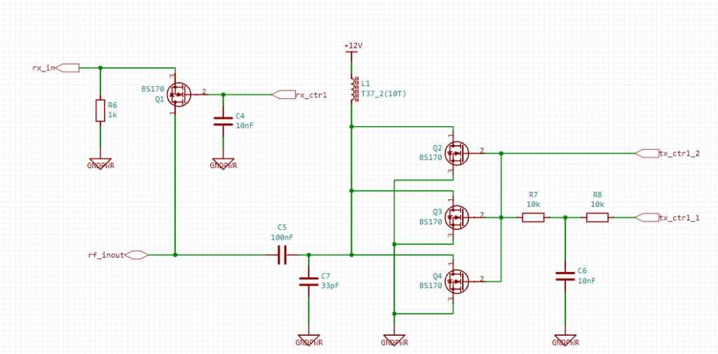
Schematic
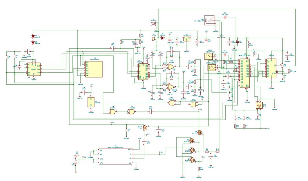
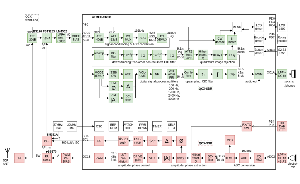
Custom release
BOM
You can download the bill of material from here:
https://drive.google.com/file/d/1dwrMmMtzmkc0MxhJFjMCbdZmg3t116QB/view?usp=sharing
All componens are coming from Mouser
To to download the PCB , you can directly order from PCBWay
https://www.pcbway.com/project/shareproject/uSDX___An_Arduino_Based_SDR_All_Mode_HF_Transceiver.html
The LPF PCB
https://www.pcbway.com/project/shareproject/uSDX_HF_SDR_TriBand_Module.html
The Build
All instructions are located in rhis following documentation:
https://drive.google.com/file/d/1E-HHCsHTksZPEKP4dhncCDxKg7idS__z/view?usp=sharing
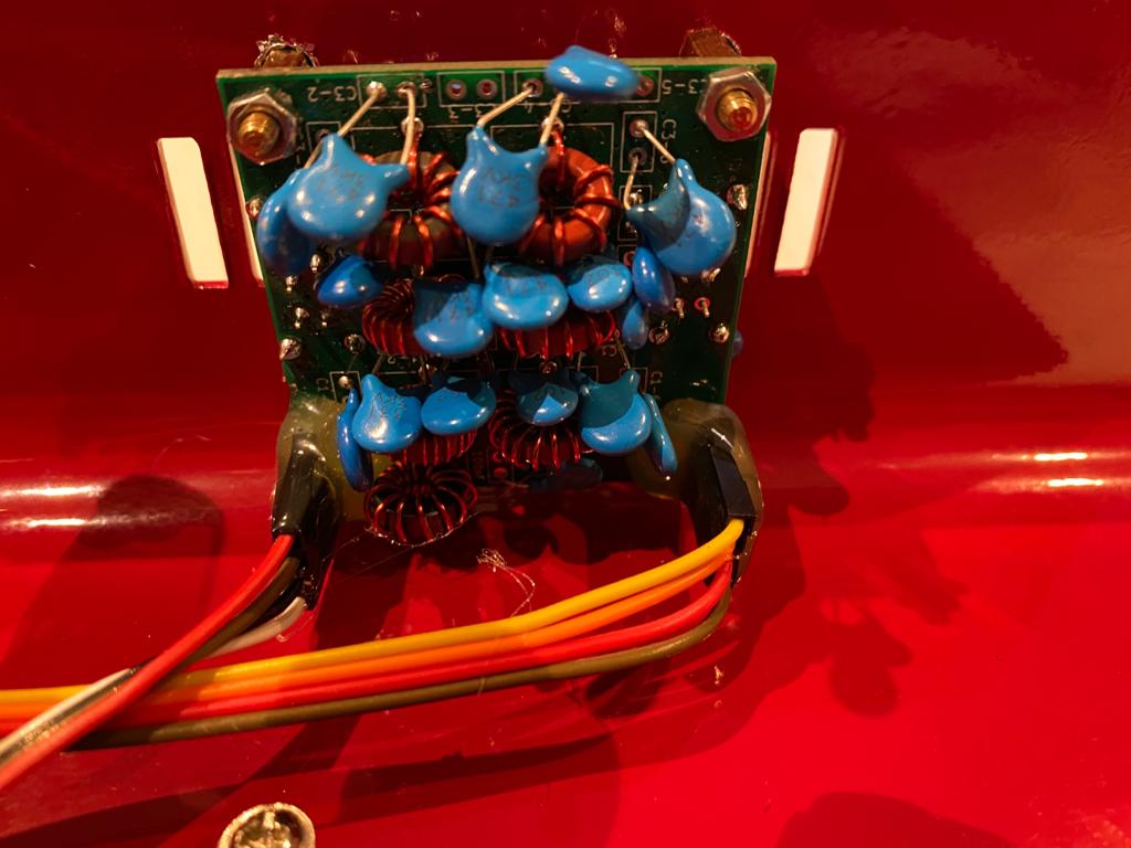
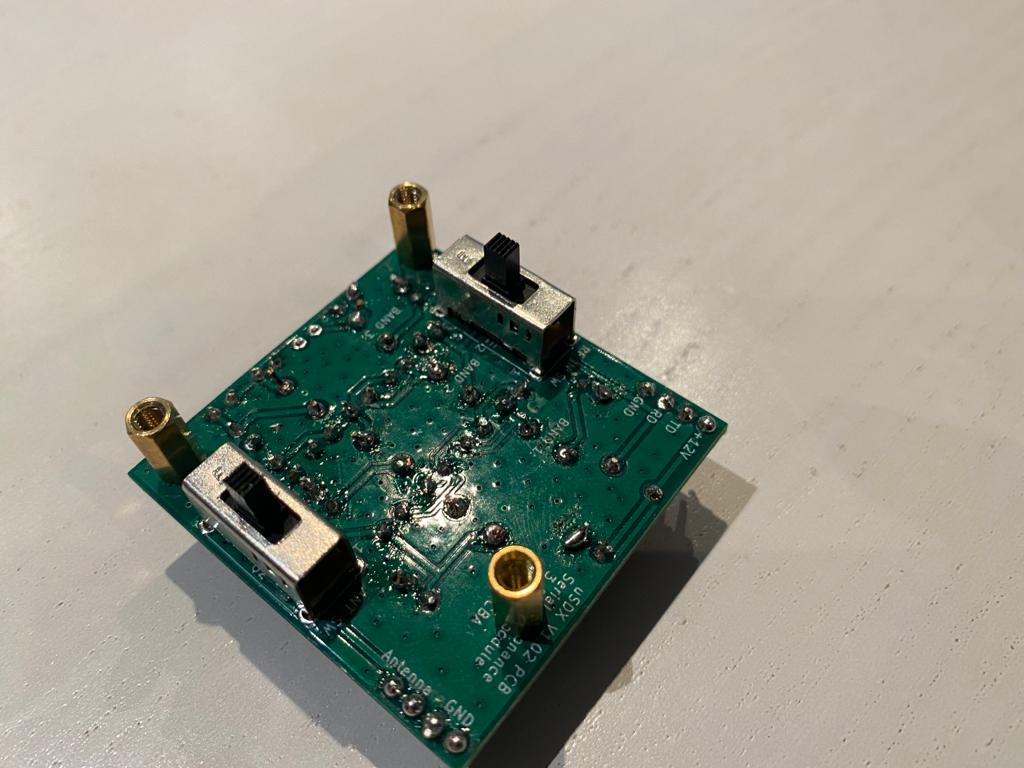
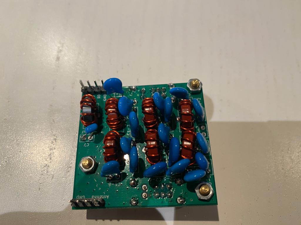
Serial Resonance LPF Band Module
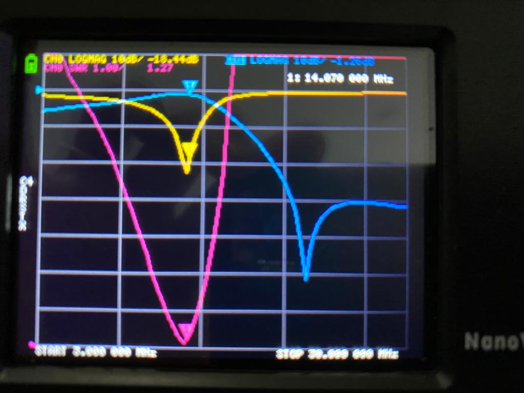
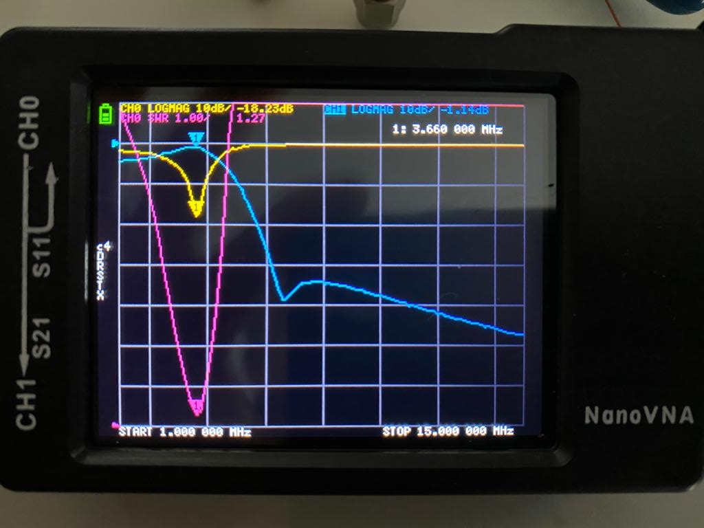
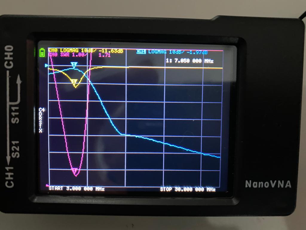
You really need to pay a special attention during the build of the LPF. A NanoVNA is mandatory for a fine tuning .
The Usdx is using a EER amplifier which is dependent with the self resonnance LPF filter . With a wrong tuning LPF you will notice maybe a great output power, therefore the output is full of spurious and IMD . The wattmeter is totally flooded with spurious and in fact is giving you a totally wrong measurement. The second side effect is regarding the modulation . A out of shape LPF is providing a terrible modulation.
You need to check the current during the transmmit and it sould be not above 200ma for 2 to 3 Watts . If your current is above 200ma (for 3w output) , your output transistors are not acting as a class E but more or less like a Class C Amplifier . Bear in mind the main benefit of class E amplifier is EFFICIENCY.
For 13.8vdc:
-Class C Amplifier delivering 2 watts , the current will be about 400ma with 40% efficiency
-Class E Amplifier delivering 2 watts , the current will be about 190ma with 80% efficiency
Efficiency of common QRP PA devices (2N7000, BS170) drops off at 14 MHz and above
- ~80 to 90% efficiency at 10 MHz and below
- ~70 down to 50% efficiency at 14 MHz and above
You can download the full guide here :
https://drive.google.com/file/d/1gTrgEr35jVqhOBLtAyXVXbll8pPXNoIN/view?usp=sharing
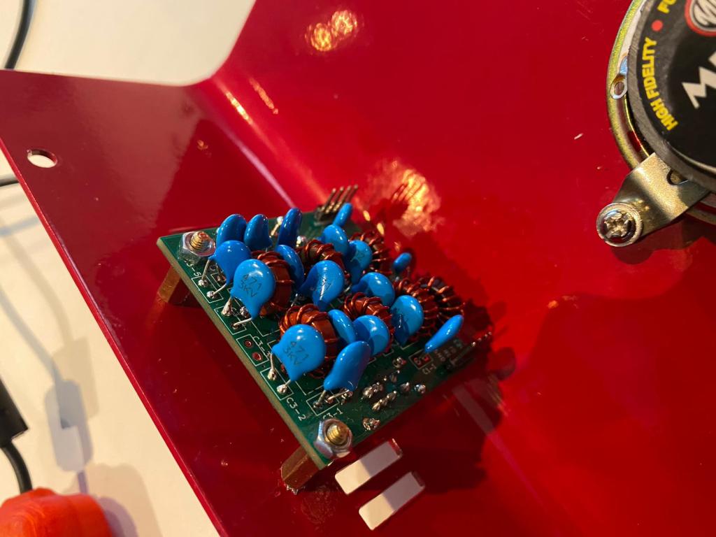
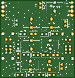
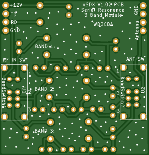
The Serial Resonance TriBand Filter Module:
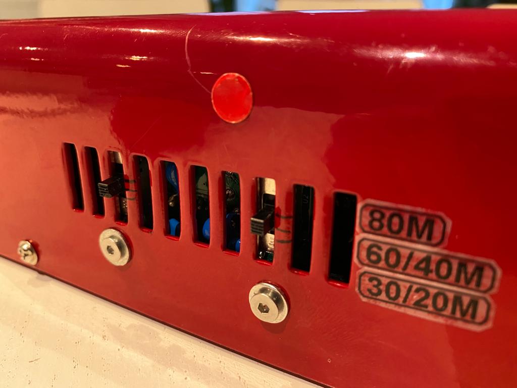
This module is also plug in type like band module but consists of 3 independent serial
resonance low pass band filters for three different bands of your choice which can be selected
with two 3 position slide switches.
Switch 1 is used to switch PA input between bands and switch 2 is to switch output of the band low pass filter to antenna.
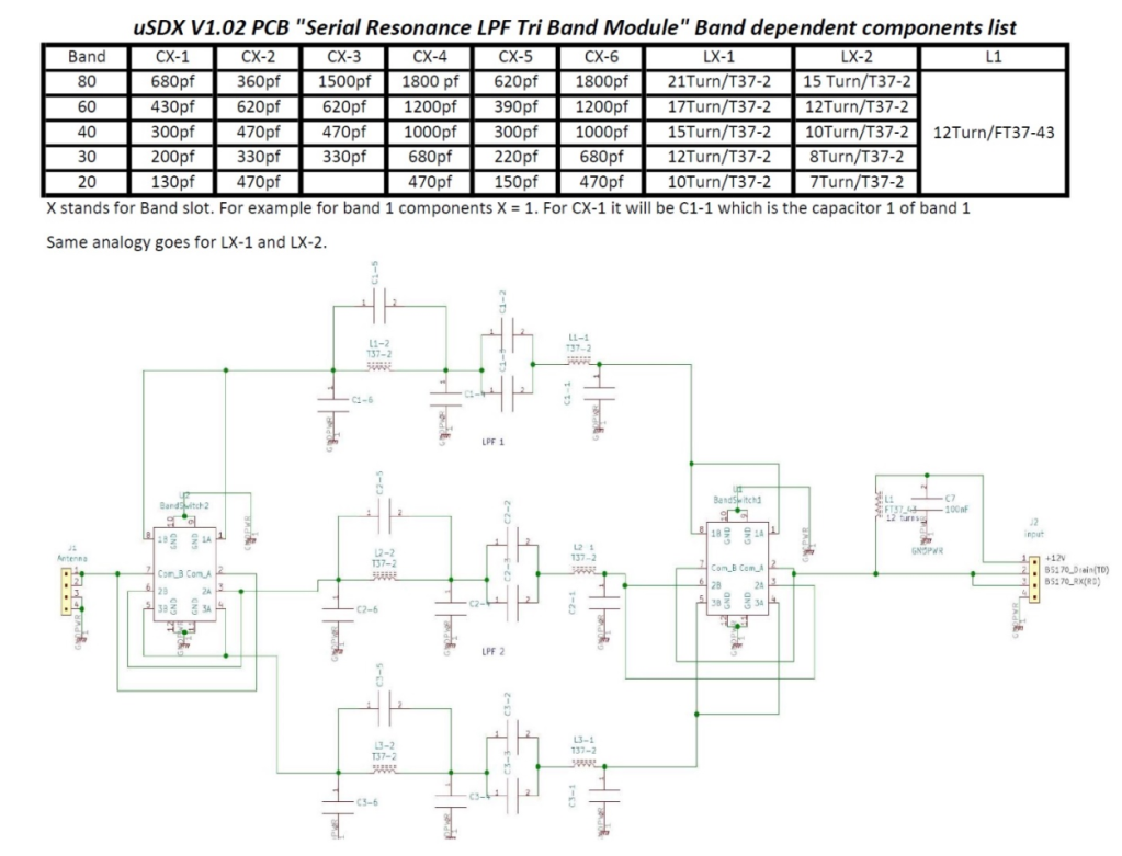
The serial resonance filters are identical in schematic and only the values of components are band dependent and varies for each band.
3 bands can be build mix and match meaning that 3 bands of your choice. Don’t forget which band slot holds which band and choose the right components from above posted table for the right band you decide to build
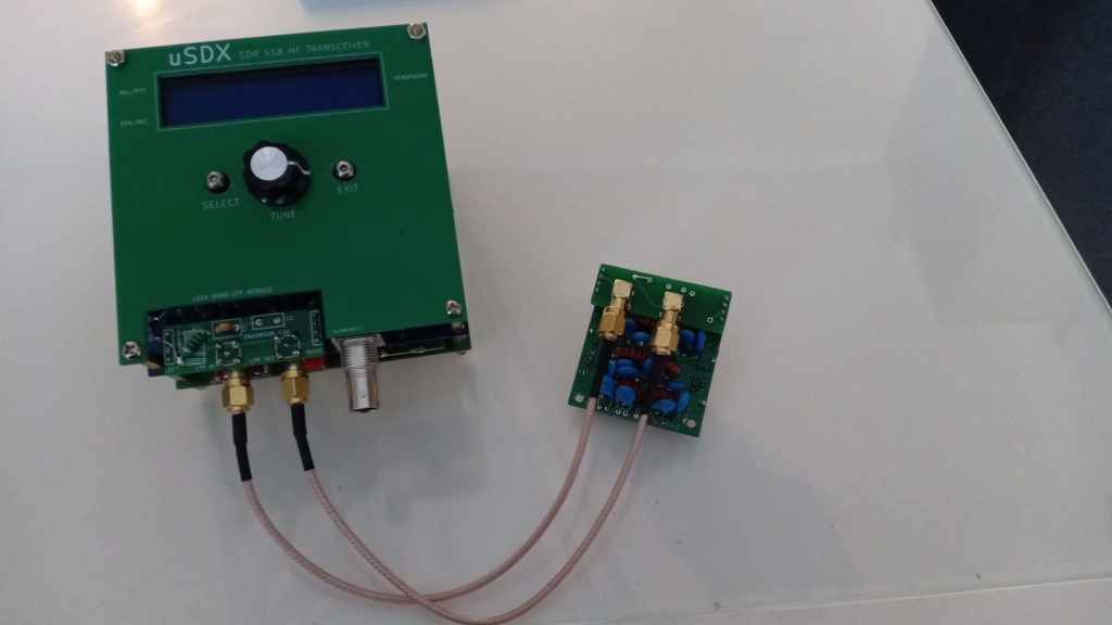
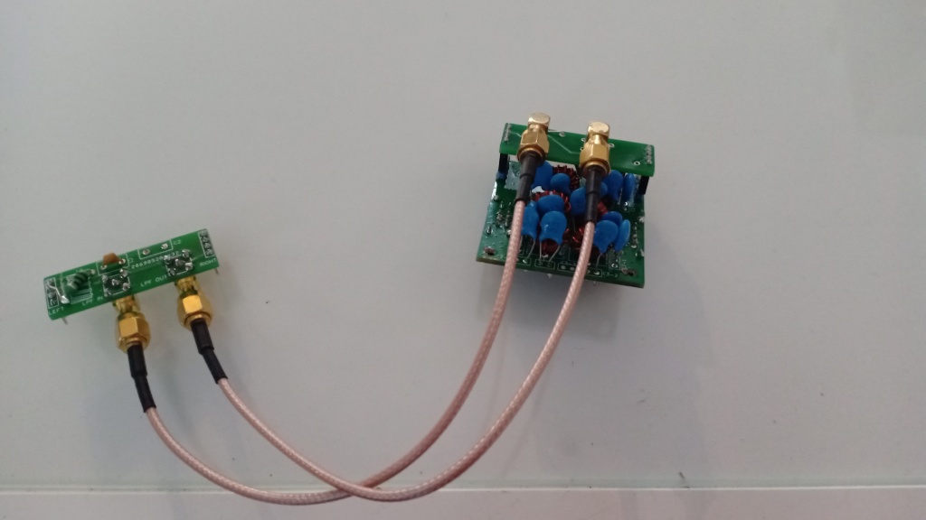
Triband LPF remote connector
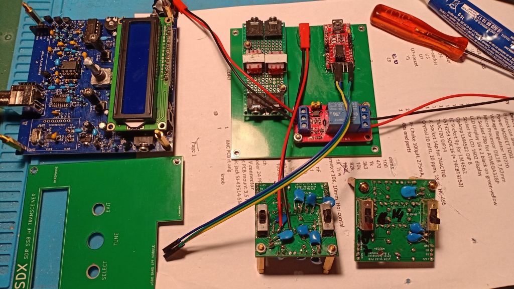
The following adapter is provide you the ability to install the 3 band LPF module remotely (Means not on the circuit board)
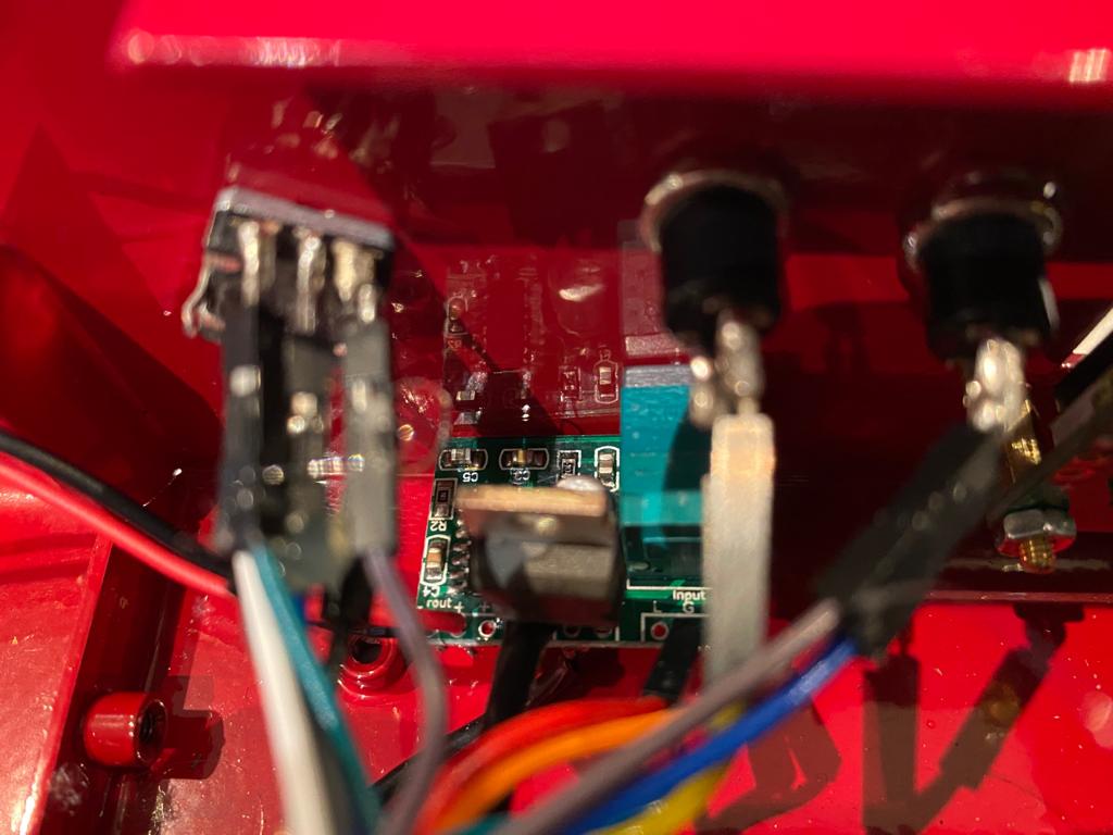
In case you are using the Triband LPF, you can use the following tiny interface in case you need to install it in the casing apart from the PCB connector:
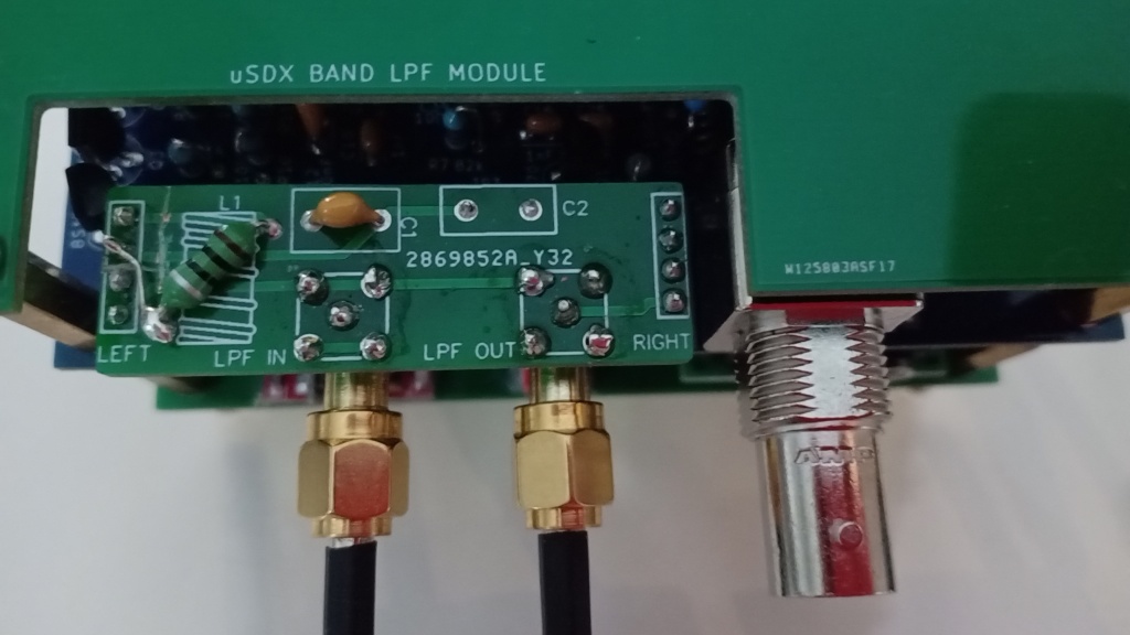

The tiny circuit in place of the LPF
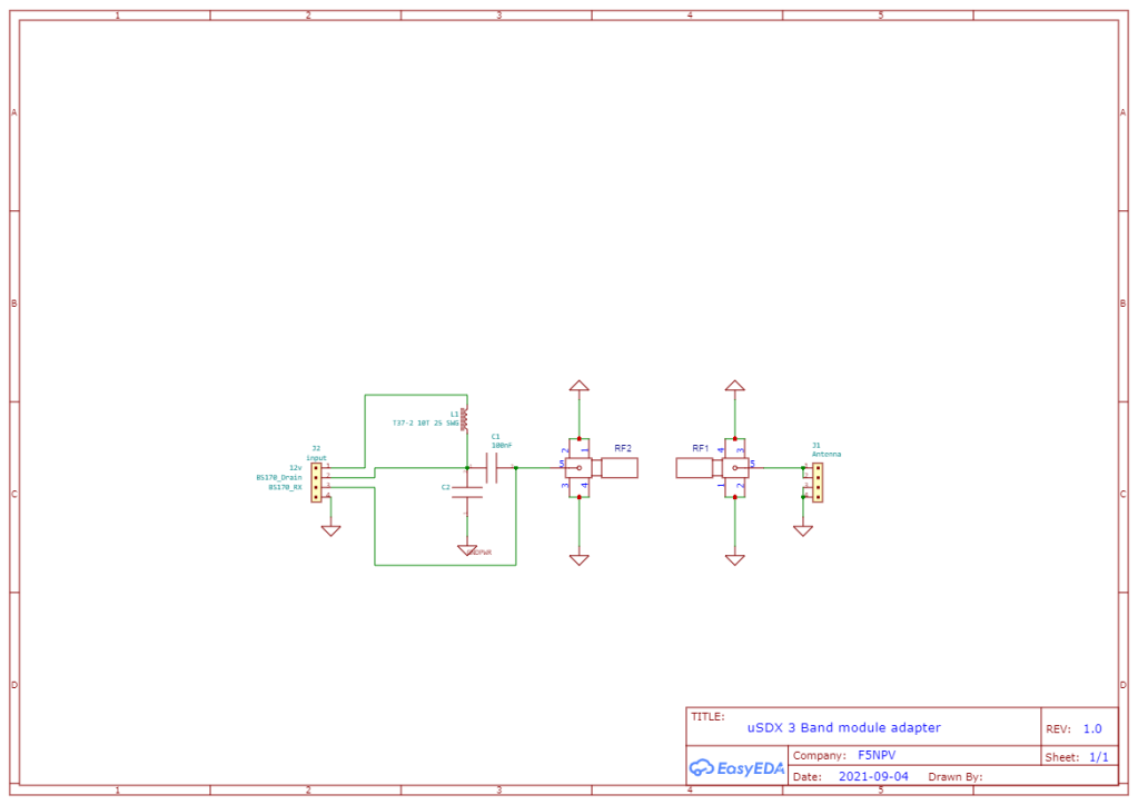
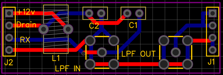
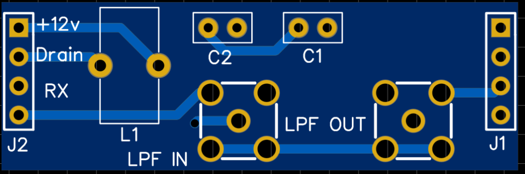
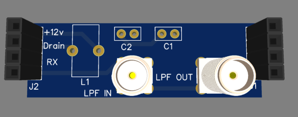
This tiny interface to be connected in place of the LPF. This interface will provide you the remote link capability from the PCB to the LPF board. The 12v for the drain network is located in this tiny interface (TD). For testing purpose i have added a 10nf capacitor to prevent the 12v to reach the LPF . I will test it like that and in case if not completely successful i can replace the C2 capacitor with a jumper. For the inductor my plan is to stick with the original design using a toroid , i will test also with a 100uh inductor.
You can find all details here : https://easyeda.com/F5NPV/usdx-5-band-module-adapter
Spectral and Modulation purity
The main issue regarding this simple design was the spectral and carrier purity which was a disaster with the stock 1.02m firmware especially for SSB mode and AF frequency above 2000hz.
According the Spectral purity and harmonics , the LPF should be perfect . No compromise and you should use good quality components (Capacitors and Toroids)
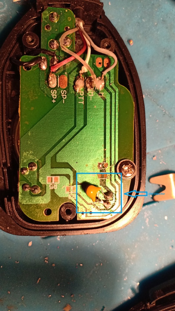
In order to correct AF and carrier purity , the following mods shall be applied:
-I am using a Electret microphone and you shoud add a 10nf capacitor between the electret microphone + and the ground. This mod is providing a basic filtering in order to prevent the AF to reach above 3Khz which was the case ( Basically the AF bandwidth with stock setup was above 4khz which is not acceptable).
-The second mod is regarding the firmware . Since we are using very simple component with limited sampling rate , a firmware modification is deemed to be in place to achieve a good spectral purity with a decent modulation quality .
You can download from here the modified firmware :
https://github.com/threeme3/QCX-SSB/tree/feature-rx-improved
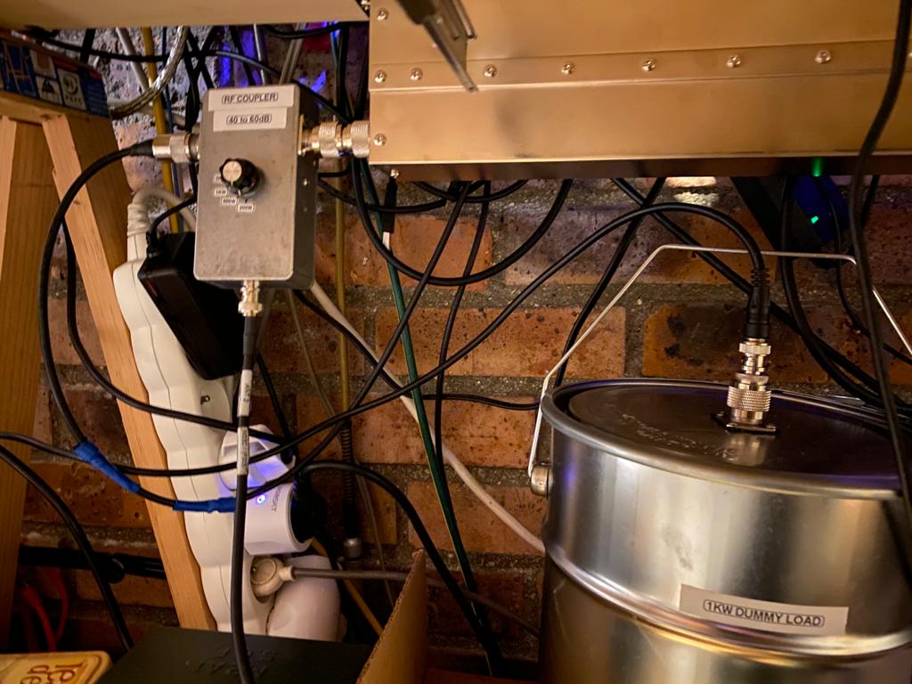
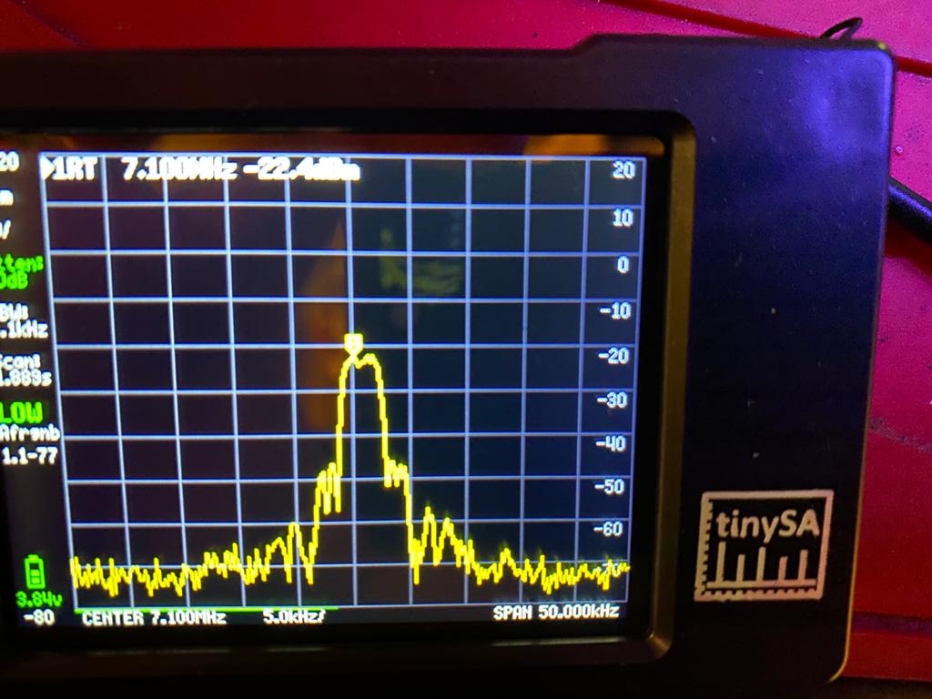
For measurement i am using a TINYSA spectrum analyzer and homemade Dummy load& Directional coupler. I can setup the attenuation in the TINYSA but also on the directional coupler
Measurement at 2watts output without the Mosfet amplifier
My LPF is providing the following performance :
-2nd Harmonic ~48 db down
-3rd Harmonic ~59 db down
All other more than 70 db down
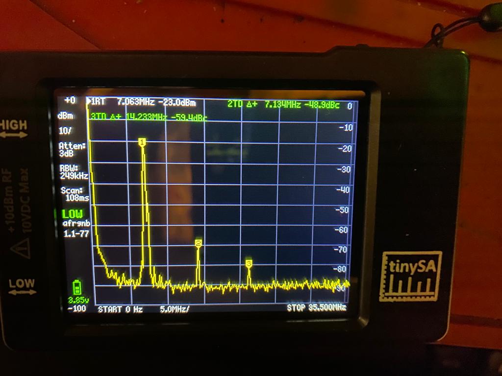
Measurement at 25watts output with the Mosfet amplifier
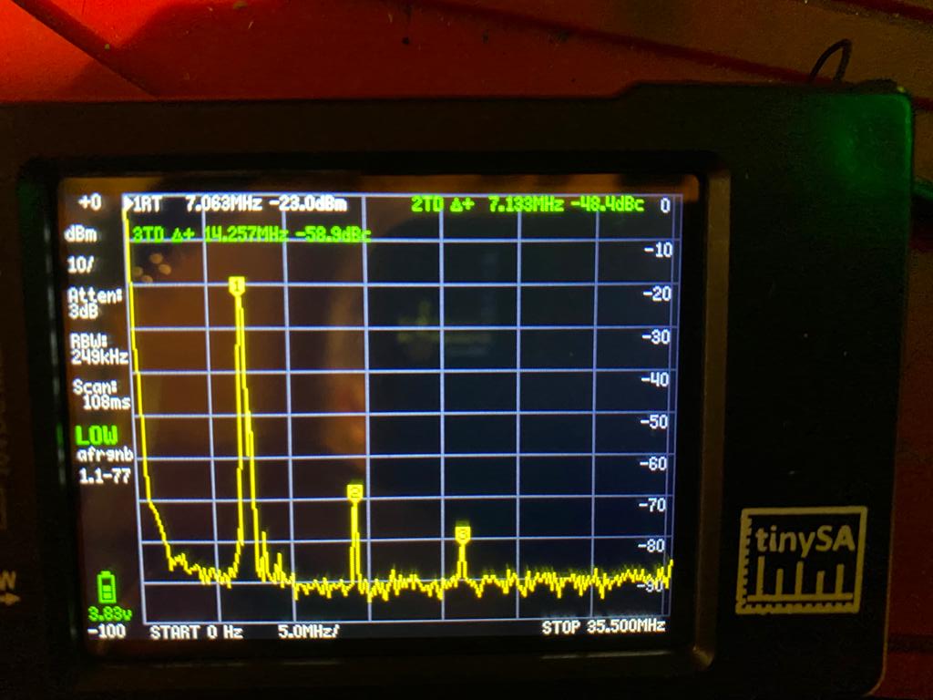
-2nd Harmonic ~-58 db down
-3rd Harmonic ~-60 db down
All other more than 70 db down
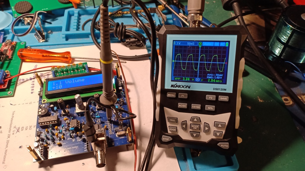
Modulation and fundamental check CW Carrier with the 25w amplifier
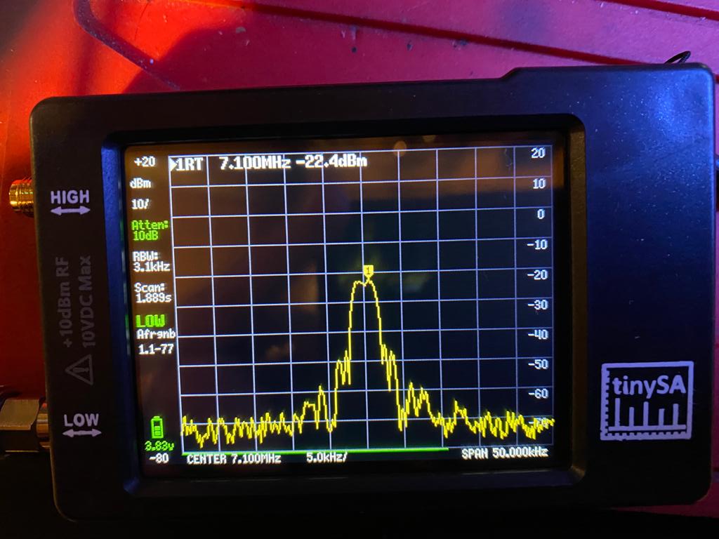
Modulation and fundamental check 1000hz with the 25w amplifier
With both measurement , the carrier is pretty much clean
SweepGen test :
Below 2.5khz the modulation is ok , above the signal is a bit saturated and was expected.
CW Carrier is very clean:
MICROPHONE AF enhancement for SSB
So far the uSDX development is still ongoing for the SSB audio quality and according with the current firmware 1.02w DIG_MOD uncomment on line #2016 , Tx DRIVE 3
In addition i add a 10nf capacitor in // with the electret cap and so far the result is not so bad and during QSO , station are reporting very decent audio quality
Some other tests with the following circuits:
So far , the best results were with a 1st order RC low pass filter with the couple 1k and 100nf , the other were too crispy or too loud.
According few QSO with OM i use to contact on the evening they report a better audio (Louder compare with only 100nf capacitor)
According the Spectrum monitoring , the IMD is improving.
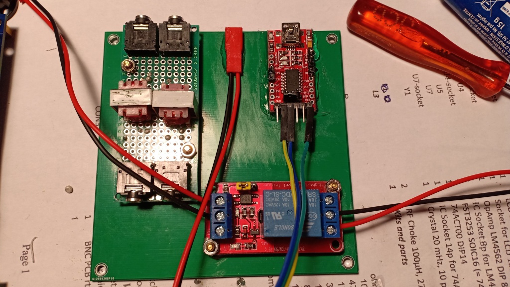
External Amplifier Control
Since i am using an external Mosfet amplifier , i adjust the biasing with the following setup :
-Min biasing = 10
-Max Biasing = 50
With this setup the output power is about 500mw which is sufficient for my MOSFET 30w
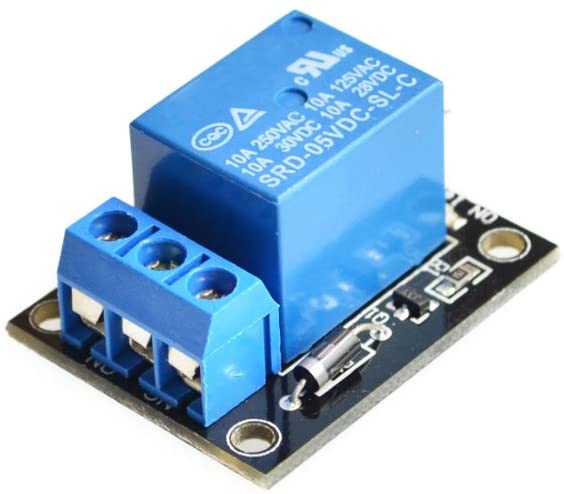
In order to control the amplifier i am using the ATMEGA328 Pin 17 (PB3) with the PTX feature. You will need to modify the sketch with the following setup :
#define BUTTONS 17 //PC3/A3 (pin 26)
#define LCD_RS 18 //PC4 (pin 27)
#define SDA 18 //PC4 (pin 27)
#define SCL 19 //PC5 (pin 28)
//#define NTX 11 //PB3 (pin 17) - experimental: LOW on TX, used as PTT out to enable external PAs
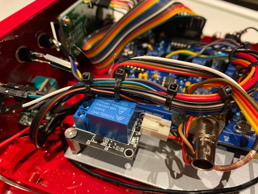
#define PTX 11 //PB3 (pin 17) - experimental: HIGH on TX, used as PTT out to enable external PAsI am using this type of relay :
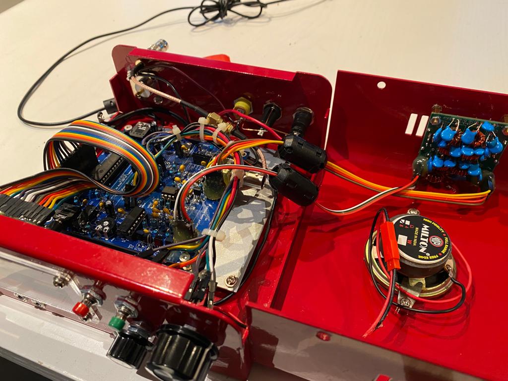
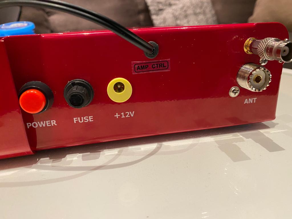
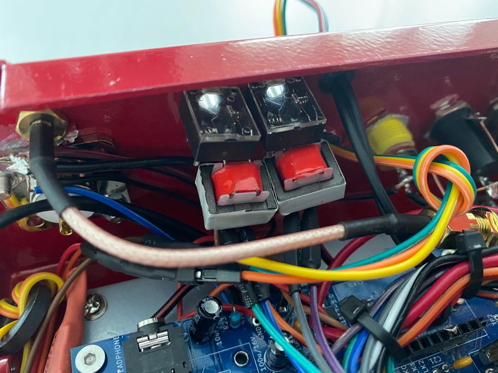
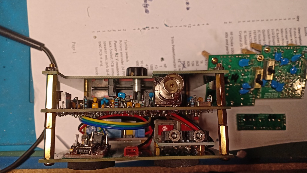
The integration in the enclosure :
Bandwidth and IMD
Since the TRX design is very simple the main issue is regarding the SSB Bandwidth and IMD during transmit.
Currently the Bandwitdth is above 2.5 kHz in SSB mode and this ssue is producing a significant amount of Spurious which are not acceptable regarding the the rules we need to rely on.
In CW mode , the carrier is pure and the spectral shape is very good.
The occupied SSB bandwidth can be further reduced by restricting the maximum phase change (set MAX_DP to half a unit-circle _UA/2 (equivalent to 180 degrees))”
This is done by uncommenting the line with a #define that sets MAX_DP to _UA/2. (the exact line number will vary by version)
I did and found that indeed the bandwidth was reduced, as shown in this side-by side screen capture of the normal released code.
According some additional test , the PWM_Max (Max biasing should be reduced in order to provide a good shape signal without splatters and IMD. Obviously , reduce the Max biasing will decrease the power amplifier output power. The test i did show me that the Max biasing optimum setup sould be below 100. The best setup regarding spectral purity for the biasing is :
Min Biasing : 10
Max biasing : 50 up to 90
Drive : 3
CAT Control
With the release 1.02m you are able to connect the uSDX to your computer with CAT control capabilities.
In the code the following line should be uncommented
#define CAT 1 // CAT-interface
There are some other CAT definition in the code but there are dedicated to CAT linux streaming using USB. According few discussions , they are not working yet.
So the following lines shall be commented
//#define CAT_EXT 1 // Extended CAT support: remote button and screen control commands over CAT
//#define CAT_STREAMING 1 // Extended CAT support: audio streaming over CAT, once enabled and triggered with CAT cmd, samplerate 7812Hz, 8-bit unsigned audio ……
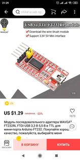
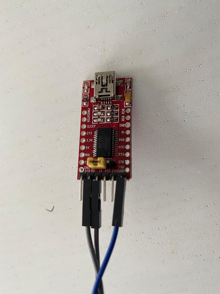
To achieve this feature you will need a USB / TTL FTDI adapter and can be purchase here :
Hamlib must be installed in your Computer
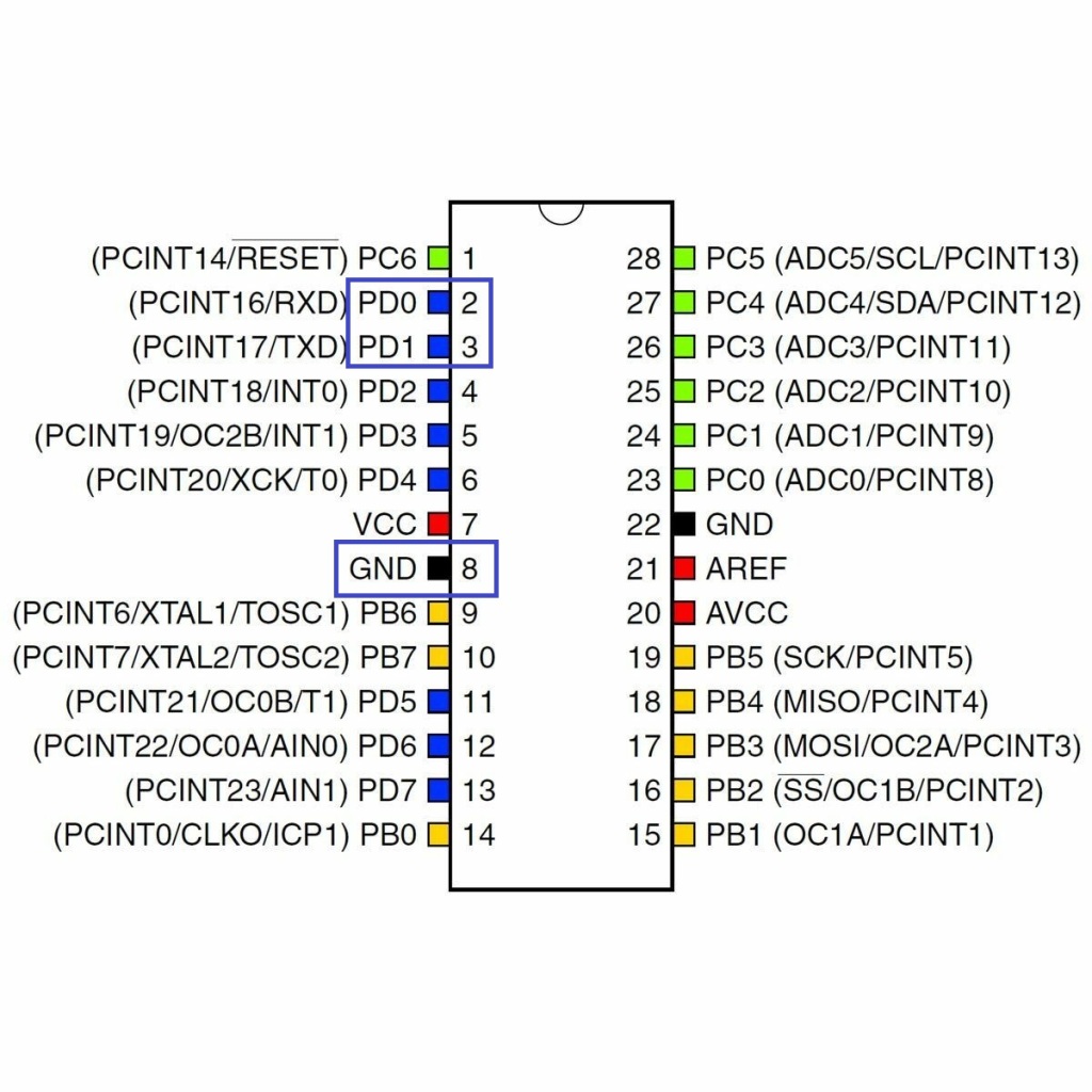
The connexion between the uSDX should be :
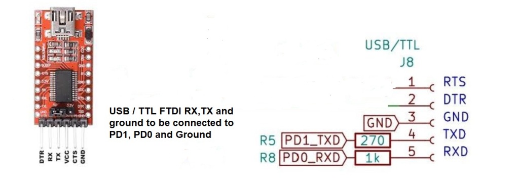
The RXD (5) from the ATMEGA MCU should be connected to the TXD of the USB FTDI
The TXD (4) from the ATMEGA MCU should be connected to the RXD of the USB FTDI
The setup on your computer is the following with FLDIG , JTDX :
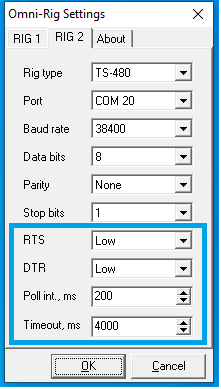
-You shall use Kenwood-TS480 in the HAMLIB or Omni-rig libraries proposed by your favorite software. My finding is Omni-Rig libraries are working very well with the uSDX.
-Terminal settings: 38400 Bd, 8 bits, 1 stop bit, no parity and no flow control. The PTT is controlled by the CAT protocol.
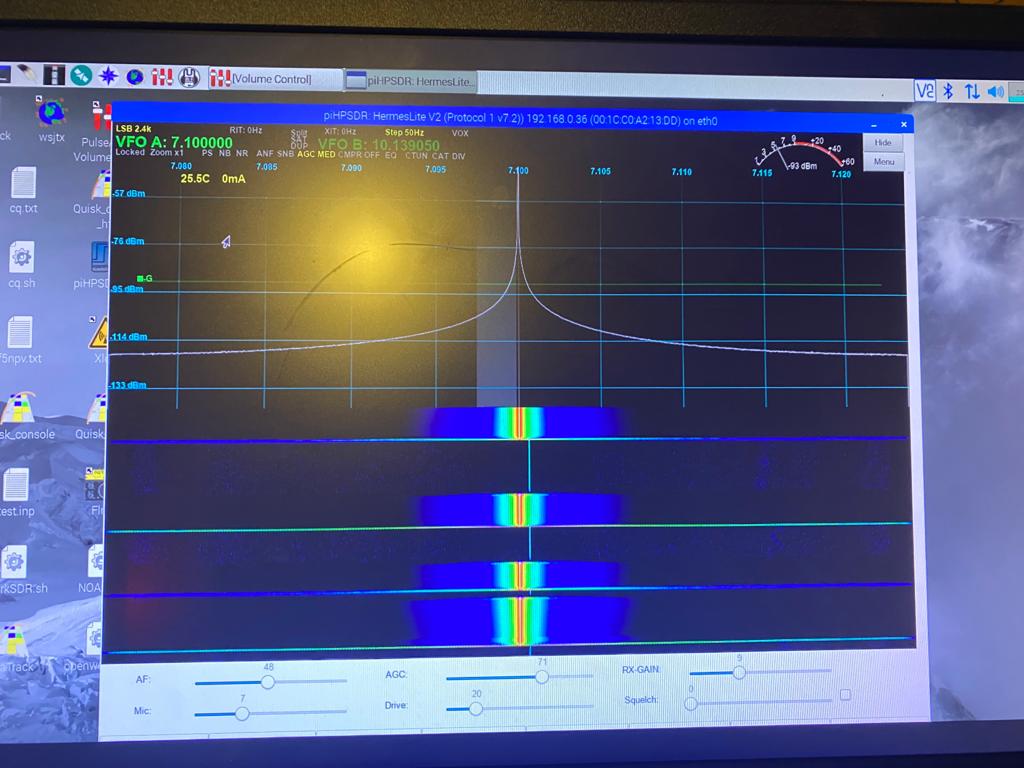
Since the CAT is shared with the LCD display , you will need to adjust some parameters on the Omni-rig interface . The most important parameters are highlighted is the blue square (Polling and timeout) . With the followng parameters the CAT connectivity is working really well and i can drive FLDIG ,WSJT-X and LOG4OM with ease:
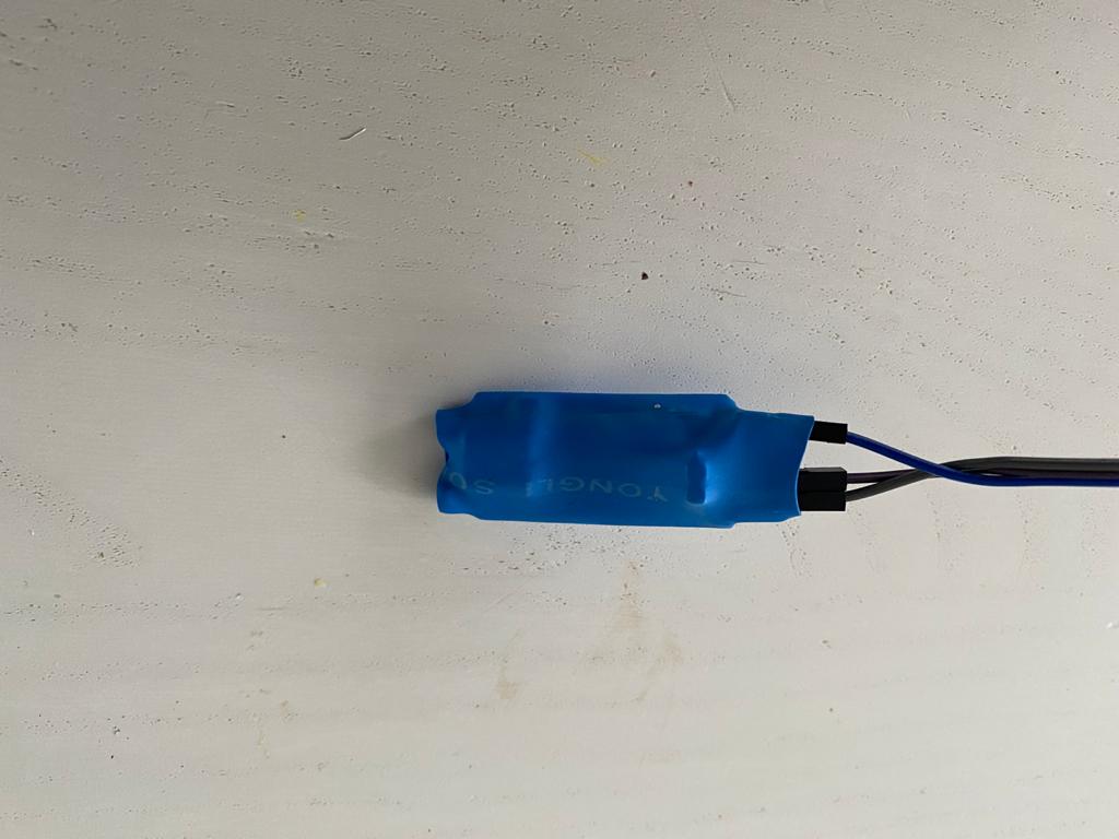
For sound input and output it is mandatory to isolate the uSDX with your sound card with 1:1 Transformer in order to provide and efficient gavalnic insulation
i have added in the menu a feature for enabling or disabling the CAT Control:

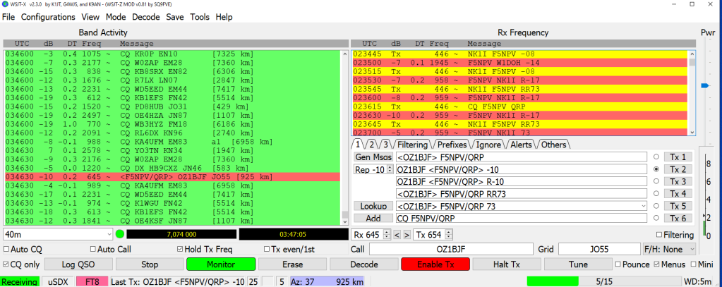
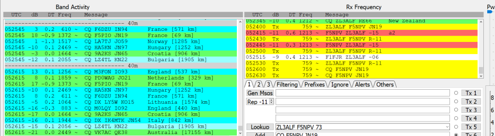
The FT8 waterfall spectrum with galvanic insulation:
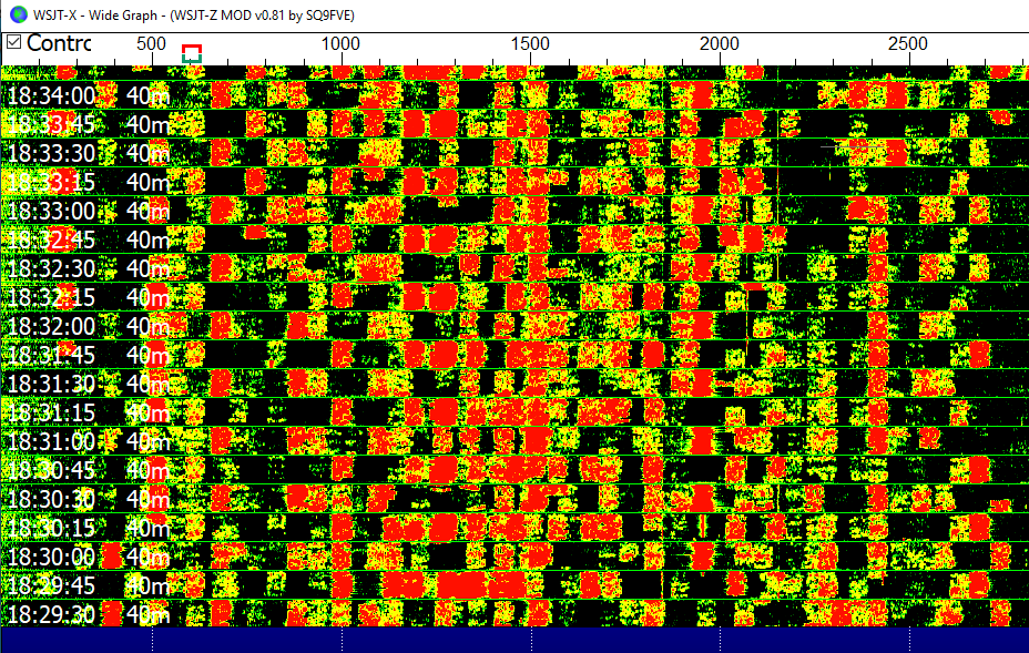
The spectrum is pretty much sharp and did not notice any significant frequency drift. i am able to decode up to -24db signal which is not bad at all
In addition i add a switch in the front panel to switch between Digital to Voice/cw keyer
For CW and DIGITAL modes the transceiver performance are not so bad, above some FT8 QSO , 20 watts with my Fuchs ENDFED antenna.
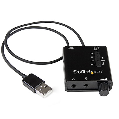
For digital modes , i am using the Startech ICUSBAUDIO2D soundcard with decent performance
Voice Receiver performance
QSO between VK2SR and OV1CVX , using my EFHW antenna
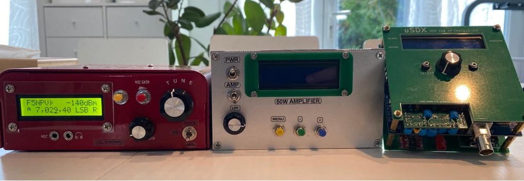
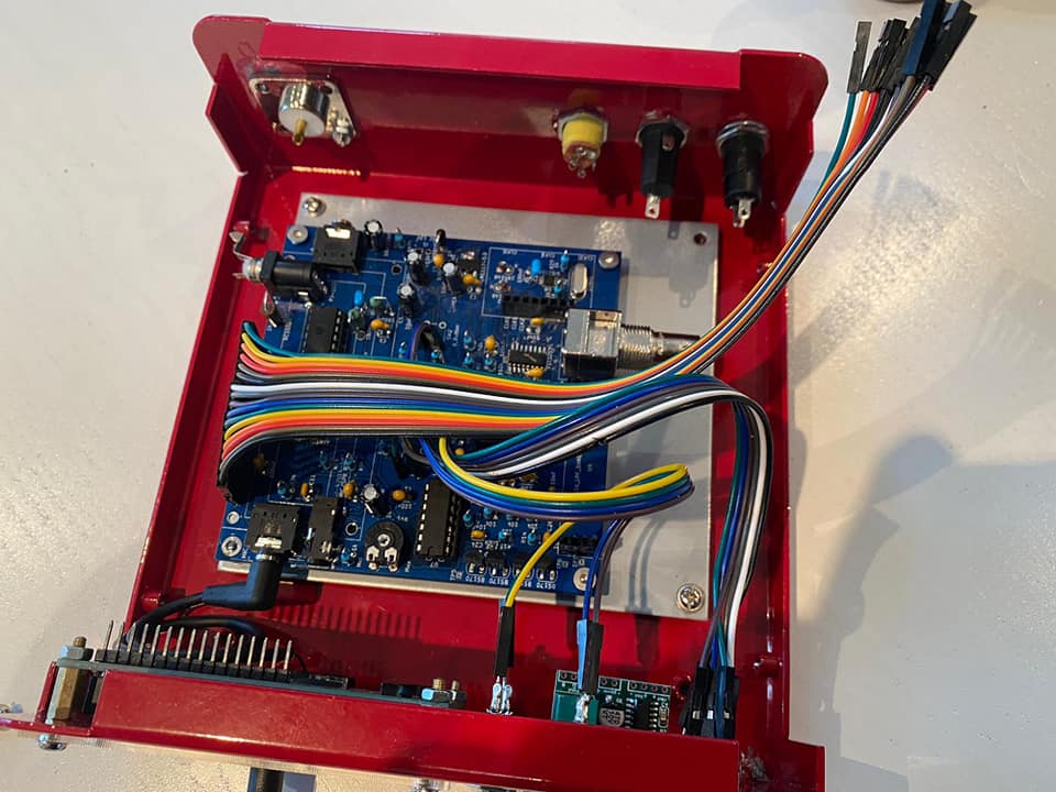
More pics
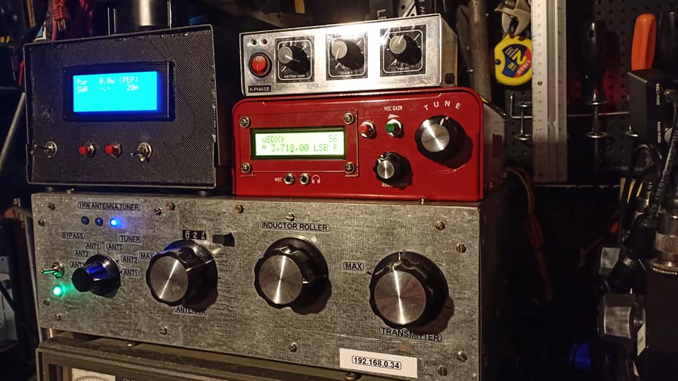
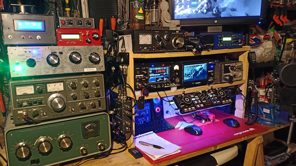
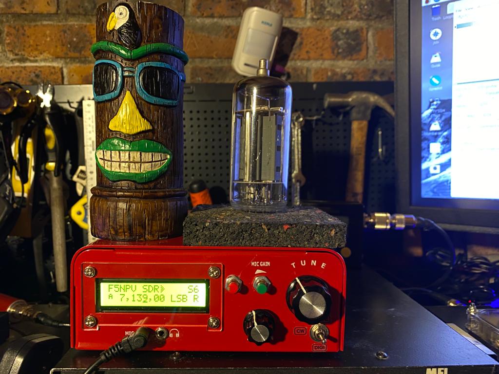
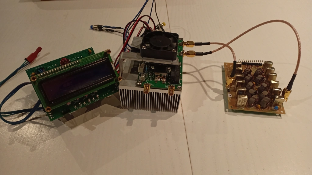
My Final Combo
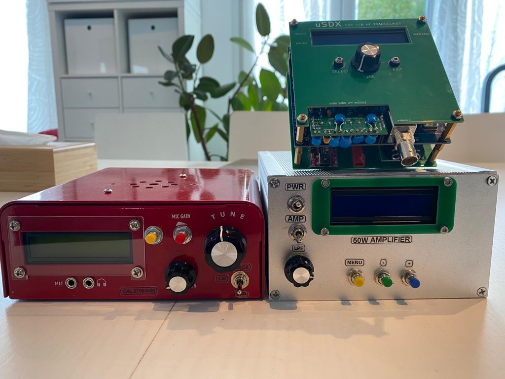
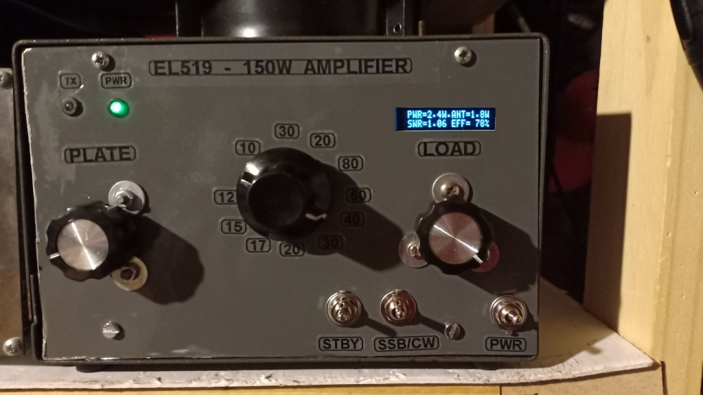
The TRX performance are really great for digital modes and CW and currently i am using this TRX with my 150w EL519 tube amplifier or a 50w MOSFET amplifier
For Digital my power is about 10 up to 40watts (2w input from the uSDX) for CW my output power is about 50w up to 80w with about 3w input.
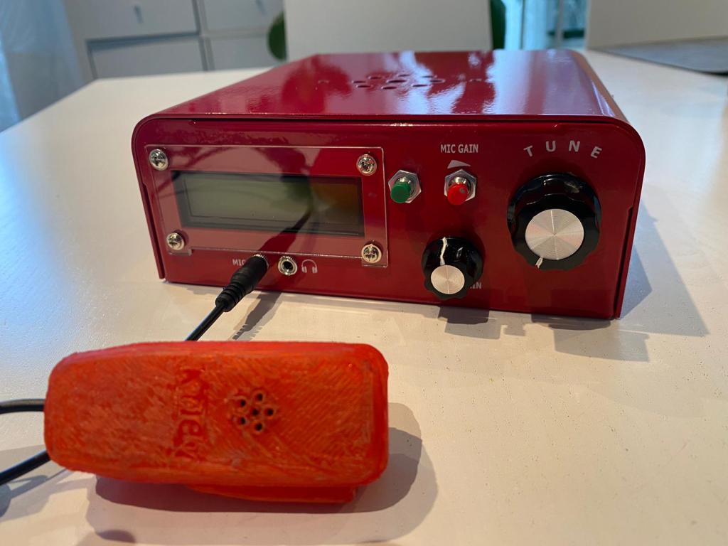
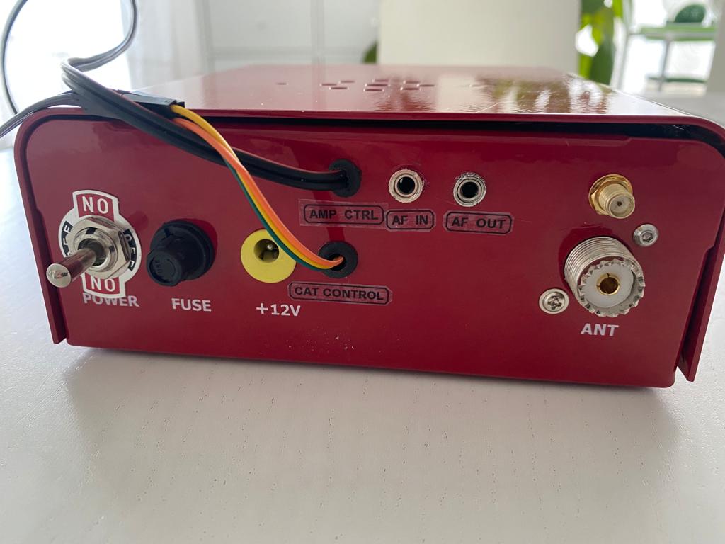
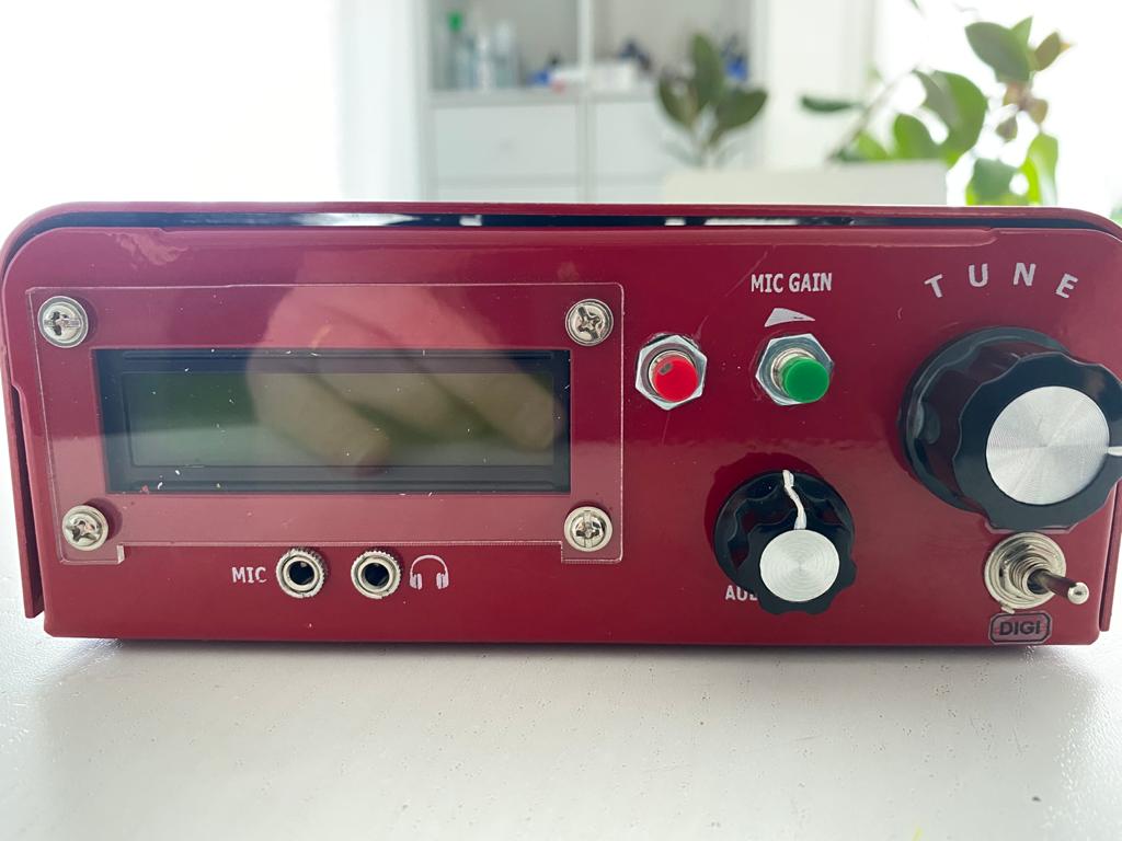
Usdx ”Big Mac” style
The latest release , very portable but with full capabilities including digital modes.
This TRX is able to :
- Connect a computer with the USB / TTL FTDI adapter for the CAT and digital modes
- A galvalnic insulation for AF IN/OUT for digital modes
- To control an external Power amplifier
- 7 Bands with 3 LPF (From 80 up to 10)
Currently this TRX is providing about 4 watts for the lower bands and about 2 watts for upper bands . A 50w IRF530 Mosfet amplifier is dedicated to this TRX . The Amplifier has automatic LPF switching capabilities thanks to a RF detection decoder based on a PIC 16F628A.
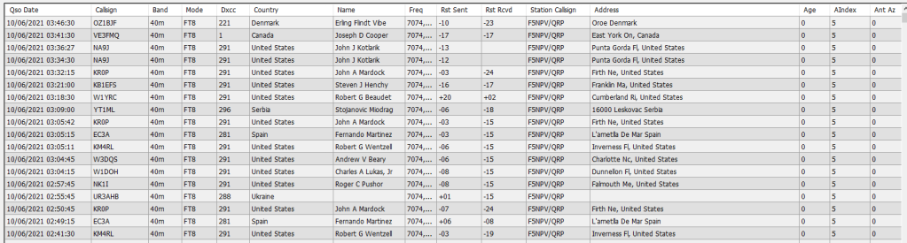
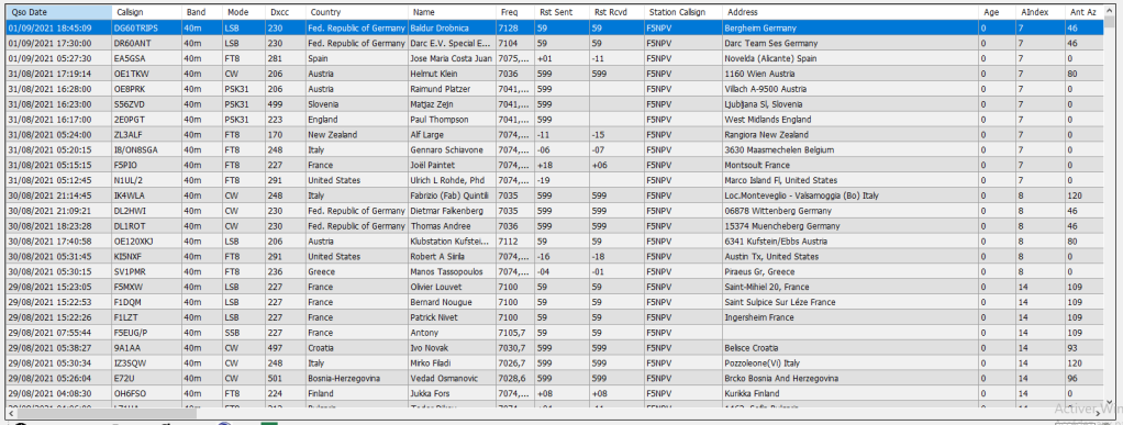
QSO and log using this TRX
During the past few days i use this TRX with power from about 4w up to 40w (CW,SSB,PSK31 and FT8 modes) and not so bad at all . For digital mode using new 1/1 transformer for gavalnic insulation has improve a lot the digital mode decoding. Great FT8 QSO with only 10w with NZ and USA.
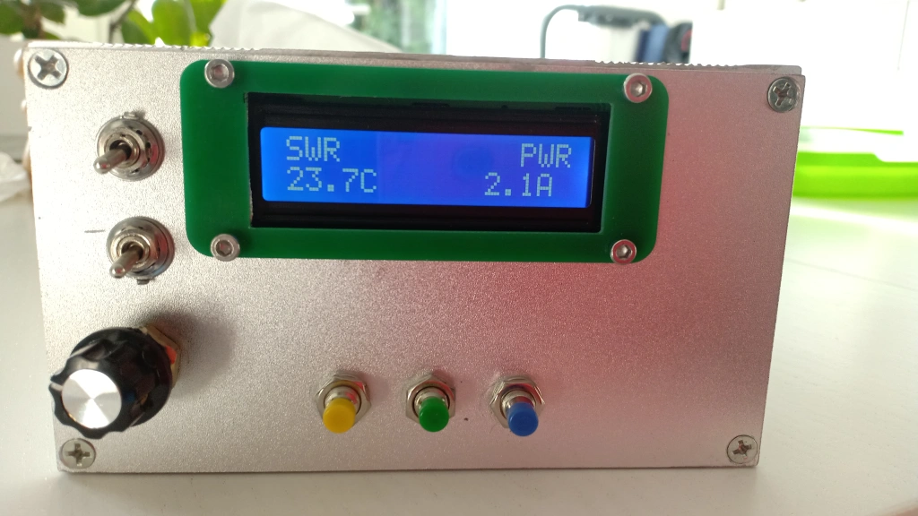
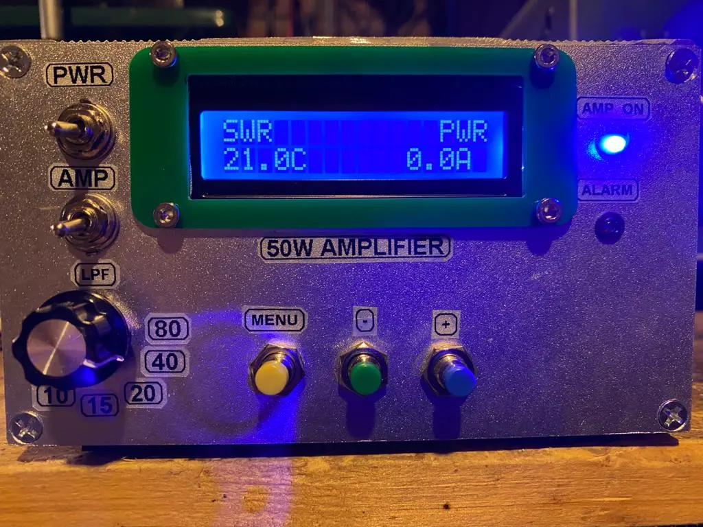
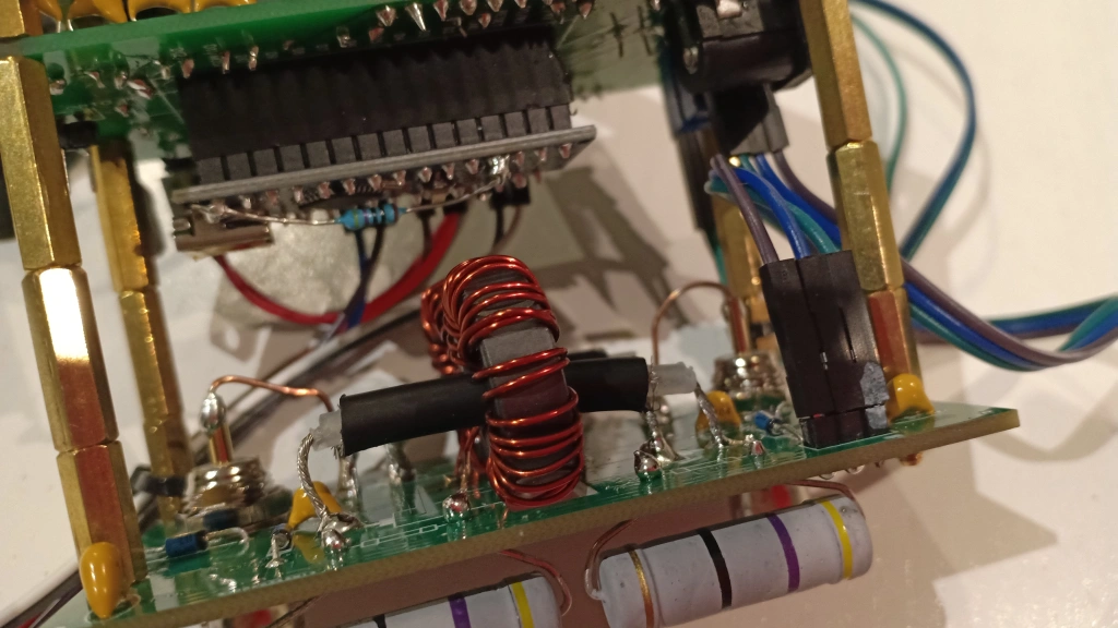
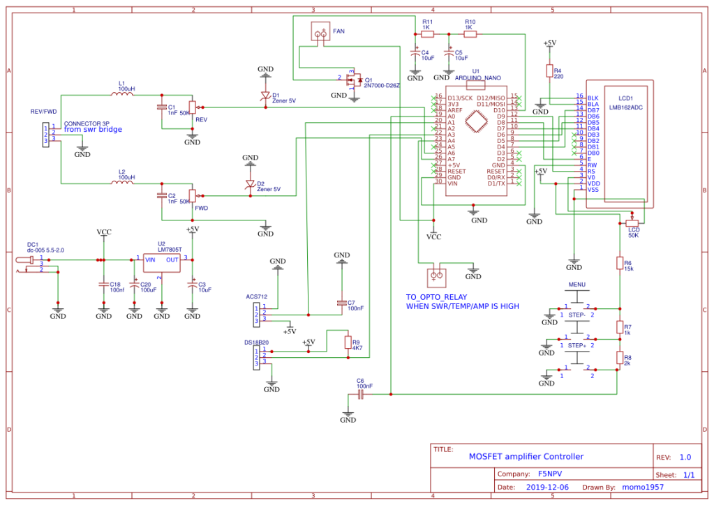
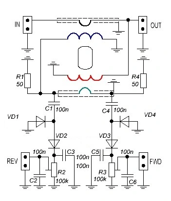
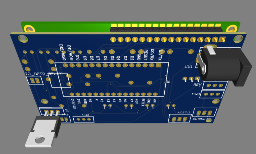
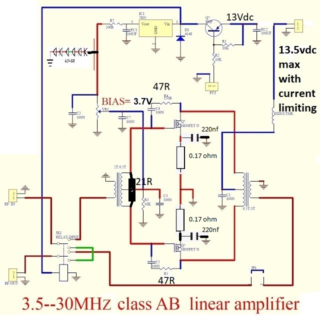
50W Mosfet Amplifier + Controller
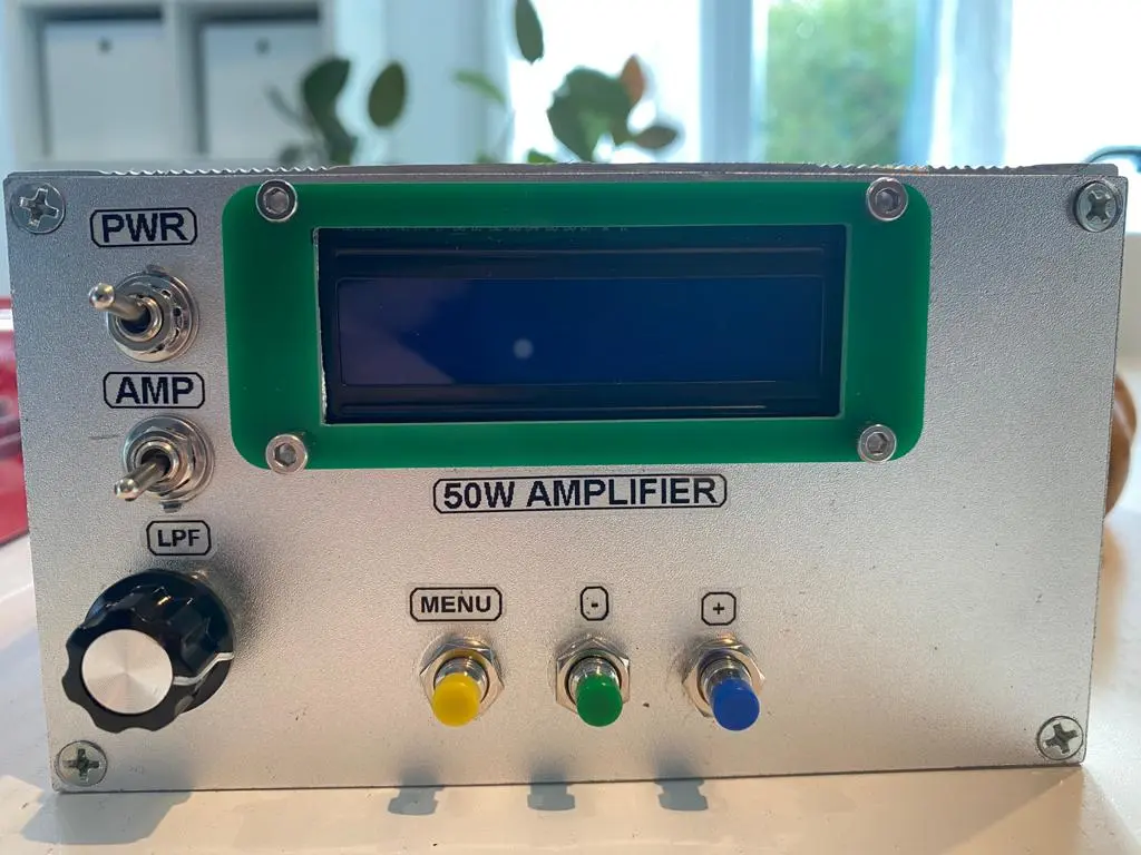
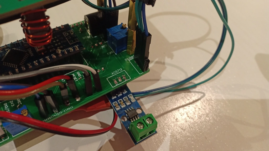
The controller is monitoring the amplifier current and obviously the SWR and output power
- The amplifier is biased with 3.7vdc with about 70ma quiescent current –> input power is 1w for about 40 up to 55w output
- The controller is providing the following capabilites:
- Temperature monitoring with dedicated menu to adjust the threshold to trigger a 12vdc Fan
- Current monitoring with a dedicated menu to adjust the max amp (Limitation) in order to cut-off the biasing with an opto relay when the current is too high
- A dedicated menu for the Max SWR adjusment –> It will trigger the opto relay to cut-off the biasing
- A dedicated menu to adjust the output power range you want to monitor . Since the power is about 50w , my adjusment is 100w which is tailoring the bargraph display accordingly.
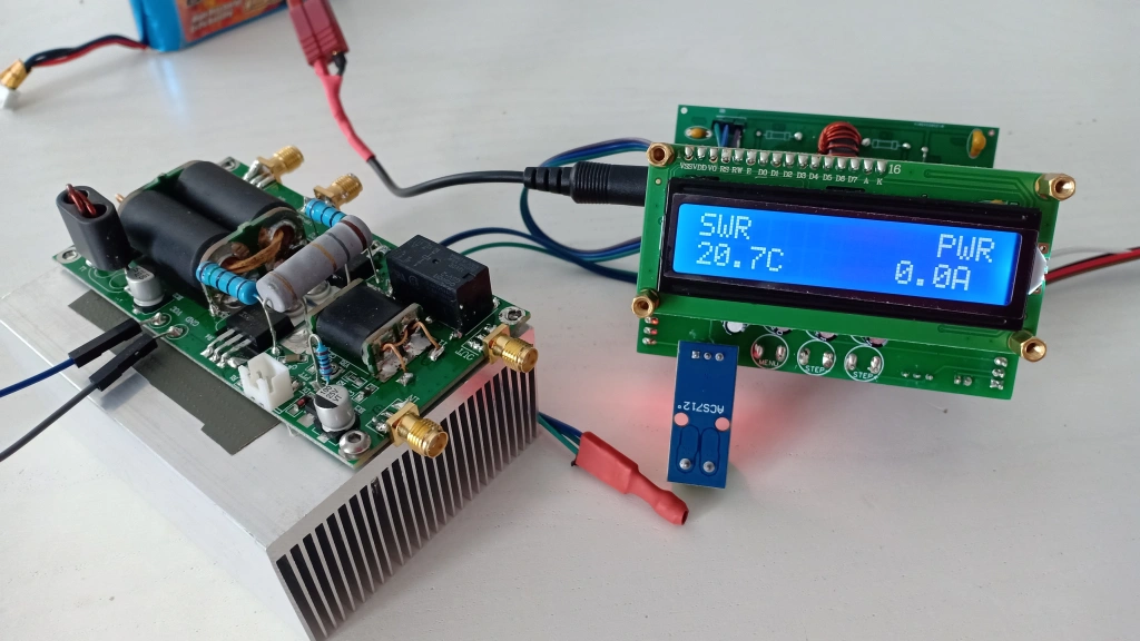
- Using FT50-43 toroids and 5w 50ohm resistor, the SWR bridge able to handle up to 1Kw
Currently i am using MOSFET amplifier for 3 years with this kind of controller with another amplifier and working perfectly.
https://easyeda.com/F5NPV/swr-meter
Arduino Sketch : https://drive.google.com/file/d/1E4R0gcUoR4Z5WwKWr_Zc6-ottOrRJNIo/view?usp=sharing

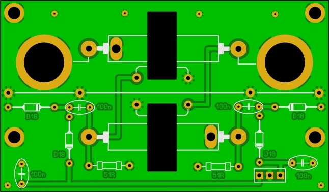
The gerber file for the SWR bridge : https://drive.google.com/file/d/1i1FAbeb4EyGl6EbUAo1TmMHviFV_yVLi/view?usp=sharing
Prior the integration with the LPF , the final tailoring was to test with some different resistor value at the secondary of the primary transformer . i manage to get a perfect input SWR with a 24ohm 5w resistor. The output power with 13.8vdc is about 50w on 7Mhz and about 30w on 10m.
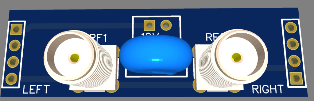
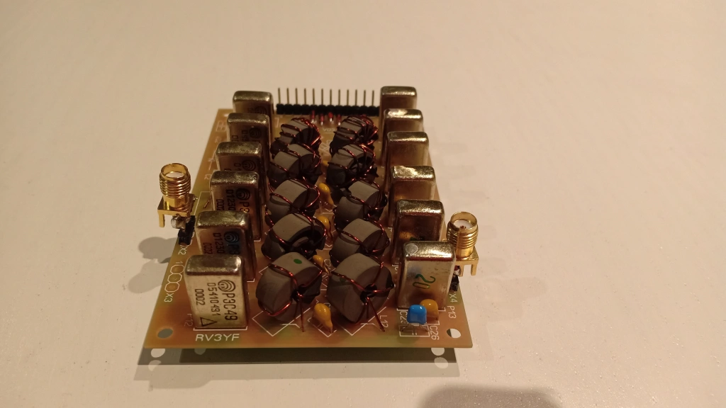
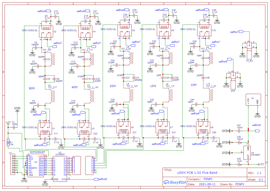
5-Band Resonnant LPF for Barb 1.02 PCB
An alternative design since i am not really confortable anymore with SMD . Getting older is terrible and my skill regarding SMT/SMD soldering is fading and nowadays it tooks me forever to solder a complete PCB (Few component it is ok). So since i am still using the Barb 1.02 PCB which is working very well the main idea is to integrate some automation LPF switching and increase the LPF available to cover the entire HF band.
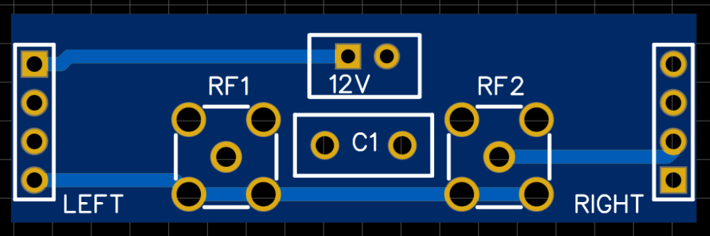
This is only a 5 bands Resonnant LPF to be used with Barb 1.02 PCB . For the integration in place of the LPF i made a tiny interface . To connect the LPF you just need 12vdc, PTX ,SCL, SDA and two SMA coaxial cable. The LPF can be easily installed inside an enclosure or in a sandwitch configuration (I guess the sandwitch is now a Big Mac or a spider hahahahahaha !!!!). There is an additional RX output to plug a SDR receiver to display the receive waterfall using GQRX .
Currently on going testing to adjust perfectly the resonnant circuit moving a bit the toroid turns. i test it only on 40m and 20m bands since the propagation sucks . currently i have at the output from 3W up to 4w from 80m up to 15m and about 2w on 10m.
To trigger the relays with the ULN + MCP + SDA + SCL i am using the octoband option from the code :
#define LPF_SWITCHING_WB2CBA_USDX_OCTOBAND 1 // Enable 8-band filter bank switching: non-latching relays wired to a MCP23008
Since using only 5 band , the following line need to be modified and you can choose the pin out from the MCP you want to use :
uint8_t lpf_io = (f > 26) ? 7 : (f > 20) ? 6 : (f > 17) ? 5 : (f > 12) ? 4 : (f > 8) ? 3 : (f > 6) ? 2 : (f > 4) ? 1 : /*(f <= 4)*/ 0; // cut-off freq in MHz to IO port of LPF relay
From now i remove the bands i am not using with this TRX.
So far so good , everything seem to run smoothly and when funnly tested and working i will publish the Gerber files (I am planning some adjustment).
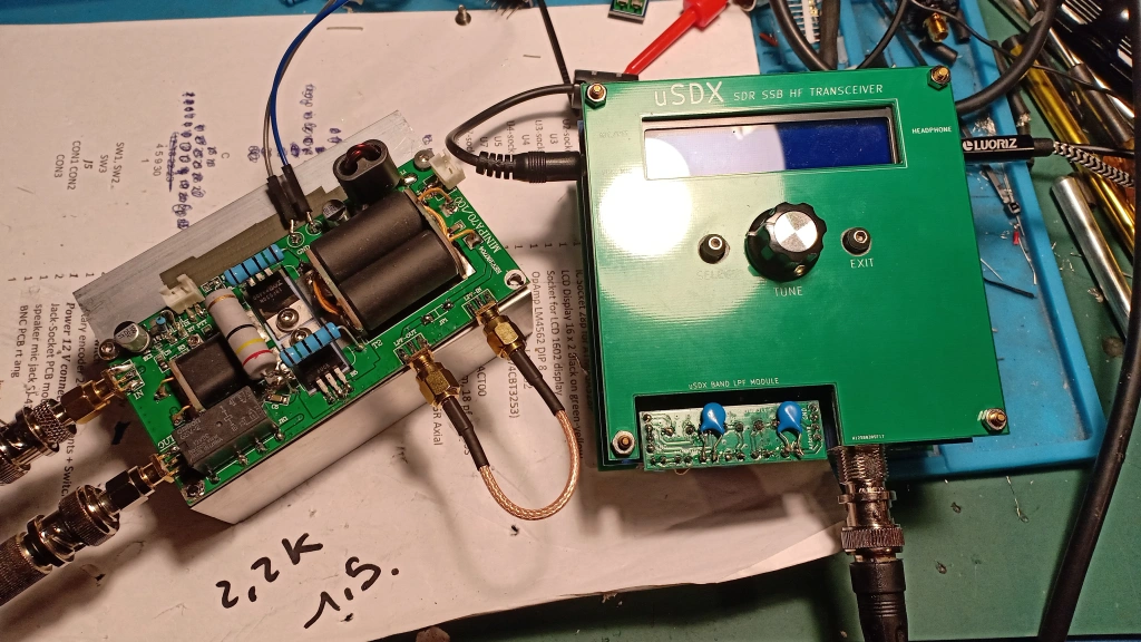
PORTABLE COMBO
Portable Combo:
This uSDX and associated amplifier are capable for all modes including digital modes. I am using a 4200mah lipo battery and i can run the amplifier+uSDX for a complete morning.

Bravo!
LikeLike
I think, yesterday during Hamfest India Demonstration Guido PE1NNZ mentioned or tried to recall your build of uSDX as an example to demonstrate uSDX capabilities.
Here’s an article you might find useful to read https://itshamradio.com/sneak-peek-of-usdx-final-version-by-dl2man/
73s
VU3HZW – Ahmed
LikeLiked by 1 person
Hello Ahmed , i did not have the time to watch the entire video , i will do tonight .
73s
LikeLiked by 1 person
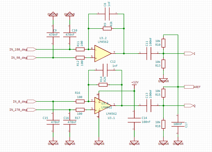
Good day, I was building your uSDX design and noticed a bad attenuation of the image channel in the receiver
I propose to install in series with the resistors R11, R16 the negative inputs of the LM4562 connect 1uF capacitors and the problem will be exhausted
LikeLike
Hello Viktor , many thanks for your input do you mean the 1uf capacitor in parallel or serial with R111 and R16 ?
LikeLike
SERIAL CONNECT capacitors 1uF to R11 and R16. DC voltage on pins 6 and 2 of the LM4562 causes op-amp imbalance and amplitude imbalance at the op-amp outputs and we hear the mirror channel
LikeLike
Hello Victor, you are right your modification will assist definitly to achieve a better balance . I will try it maybe his week end
73s
LikeLike
There are still improvements regarding the uSDX transmitter, if interested, write to me in the mail My CALL RA9OAU
LikeLike
Hello Victor.
Could I have some information regarding improvements to USDX radio both receiving and transmitting.
Thank you and best regards.
LikeLike
Hello,
No particular impovement. The Usdx is an experimental transceiver and regarding the design you cannot expect for example a good audio in particular in SSB during transmit. the hardware limitation will prevent that. In addition in SSB transmit , the IMD in totally out of specs. The Usdx is a good TRX for experimentation but not really nice as a main transceiver in the shack.
73s Didier
LikeLike
I also want to show the modding of the transmitter between gate bs170 and RC filter on R14, R15, C26, you need to install an operational amplifier LM358 pin1 and pin 2 between shorted to each other and connected to GATE BS170 Q2, Q3, Q4 through an inductance of 500uH, pin3 is connected to RC r14, r15,c26. lm358 must be powered from 5v. transmission quality becomes much better than assembled according to the scheme
LikeLike
Hello Viktor,
Sounds great . Currently i am dismantling my shack because i am moving to another country . Not sure i will have some spare time to implement all mods. When installed in my new location i will work on it . I have a spare Usdx and using it for testing and modding . So when i will be installed in my new location i will have some spare time . Unfortunately since i am moving to South East Asia my moving and stuff will take a while to reach there ; I am assuming i will be ready and shack up again sometimes this coming summer.
Btw i appreciate a lot your inputs and definitly it sounds promising . For now it is packing time and mostly cleaning time since i have so many junk in my shack .
We keep in touch Viktor
73s Didier
LikeLike
If you are interested, try it I got the quality of the SSB signal with almost no wheezing and distortion, always happy to help RA9OAU 73 SK
LikeLike
If you make a modification of PA, put the video on the site, I will be glad
LikeLike
well, I understand you and I wish you good luck and well settled in a new hut with radio junk
ka and me so that you have plenty of room for antennas and continue our great amateur radio activity 73 tu ..
LikeLike
Bonjour,
Great work in a True ham spirit
I really like what your are doing.
Hope to meet you one day in a french ham event.
73.
Ghislain F4HGA.
LikeLike
Hello Ghislain
i try my best but the good thing is mostly because of the input from other Ham with very interesting comments , suggestion and question and this is really all about .
Next week my shack will be totally dismanteled since i am moving for good to South East Asia . I will be V85/F5NPV for 2 and most probably 4 years and after that i will be retired in Malaysia with a local 9M? callsign. Obviously the Website will still active.
73s and hope to hear you soon from V85
F5NPV
LikeLike
I am very touched by your words I like this design and I want to bring it to perfection as much as possible now I am upgrading the usdx transmitter and I managed to remove the distortion of the signal to the transmission to a greater extent
LikeLike