

Homebrew LMR SDR TRX Design
This project is a variant of this following design from UT3MK https://ut3mk.at.ua/ , the AVALA SDR from http://yu1lm.qrpradio.com and YE3CIF SDR TRX : ye3cif.com/lmr-sdr-transceiver-10-160-meter-band/. Basically the design is a variant of the SDR-1000
Since this project is now finalized you can find it on PCBWAY and Arif YE3CIF has compiled the overall files here (Many thanks ARIF for your desing and this wonderful TRX) : https://www.pcbway.com/project/shareproject/SDR_Transceiver_10_160_meter_band.html
The SMD variant of this transceiver from Yuri UT3MK with additional features. This TRX is using THD and the only SMD is the SI5351
https://www.pcbway.com/project/shareproject/SDR_TRX___Super_Puper__synthesizer_.html
https://www.pcbway.com/project/shareproject/SDR_TRX___Super_Puper__main_board_.html
The TRX is covering from 160 up to 10m band and the final design is a compilation and integration from various sources. This is a very international project from Indonesia , Ukraine and France.
Hereafter a SDR TRX design example from the UT3MK Forum.

The modified one with about -10-17dBm (0.1-50mW) output and the Band filters BPF relays are triggered with a 74LS145N which is providing the capability for up to 9 bands external LPF for the external amplifier. I am using a 2N3904 for the 50mw transmit amplifier and a BS170 for the receive preamplifier. Since some guys got some issue with the I2C LCD (Spurious and spikes during receive) , i am using a standard LCD without I2C.In addition , we are using only one CLOCK from the Arduino Nano (CLK0).
This SDR transceiver is using only 5 integrated circuits and 5 transistors. The arduino Nano is used a a clock generator and controller. Some Designer are using the STM32
The other differences are regarding the IQ mux (74HC4051) , the AF amplifier and we are using also different circuit with hopefully better performances.
The CD4051 is used as a quadrature detector. This chip is widely use and bring great performance for the symmetry of both analog I and Q paths.
The design is allowing to use a 25Mhz or 27Mhz Cristal and this can be setup with the main Transceiver menu.
The remote push buttons to change the mode and so on are removed in the final design
The 30w amplifier is already done and the main board is already equipped with LPF switching capabilities for the amplifier.
To feed the final amplifier , i use a class A amplifier in order to provide about from 1 up to watts output power.
This new design is able to provide the oportunity to use the device with PowerSDR and ExpertSDR software. The VFO is controlled , from PowerSDR or from the front panel encoder.


An audio file from a QSO with PA3GEG
https://drive.google.com/file/d/1l8_uWAo1qHF3YkrUUEFv2ESnOPERUudP/view?usp=sharing
A QSO with Callum M0MCX
Final Schematic and Design
You can download the schematic here : https://drive.google.com/file/d/1V3bzmcbPLV4xXfHAe0pxwMqRyku0o9NY/view?usp=sharing


Transceiver in details
This transceiver is covering from 1.8Mhz up to 30Mhz.
Basically the TRX control from POWERSDR is based on the SDR-1000 TRX with obviously some differences (A lot in fact) and the main one is we are not using the LPT port since everything is controlled by the CAT protocol (Kenwood TS2000) from the Arduino Nano only.
The transceiver is not a DDC/DUC with stand alone capabilities and it is a front-end using a soundcard for IQ detection. Bandwidth 48/96/192 depending on the sound-card. PowerSDR or ExpertSDR software are used to control the overall features.

The overall cost was:
55€ parts (Components and the PCB)
30€ Case and knobs
40€ 30w mosfet amplifier + Low pass Filter
80€ ASUS XONAR U7 MKII Sound card
Overall cost is about : 200 € , so needless to say this is cheap regarding the performance you can acheive and the pleasure to build and setup your own equipment .
The transceiver is the following set of functional units, combined on one board:
• This modified SDR transceiver based on the developments of Alexander US5NCJ, YE3CIF and UT3MK;
• synthesizer on Si5351 under Arduino control .The original arduino sketch is coming from UT3MK Forum and currently i am using the modified firmware you can download here : https://drive.google.com/file/d/1phx2hHXN3ZEg8itbpfaa1rRcNI_zXIEN/view?usp=sharing
• band-pass filters for 9 ranges, for low frequencies individual, for high frequencies combined; The filters are controlled with a 74LS145 with BCD-TO-DECIMAL inputs from the Arduino Nano
• controlled attenuator for attenuation of the received signal by – 20dB; in addition you can find a preamplifier capabilities with up to +10db amplification for the receive signal
• control unit for external low-pass filter for power amplifier.
As an indicator, a 16×02 LCD display is used, connected to the Arduino and you are able to monitor also the output power and SWR.
RF Power Amplifier is deliberately not in this projet, you can combine it with any RF Power. The output of this Exciter is about 10-50mW.
Currently i am driving a IRF530 Mosfet amplifier (10w) but i have just achieved the intégration of a class A + LPF amplifier. The integration is providing a great and perfect spectral purity . The Class A outpout power is about 5w watts which is perfect to drive my EL519 amplifier for a final output power from 80 up to 100 watts.
Below in this webpage, i put 2 amplifiers design base on 2n5109 and IRF530. i am still experimenting the 10w amplifier and currently it is very promising.
Synthesizer on Arduino + Si5351
This synthesizer is designed to work with an SDR transceiver in conjunction with modifed PowerSDR software initially used for the SDR-1000. The frequency of continuous overlap when using the original synthesizer microcircuit is from 1 MHz to 30 MHz, the upper limit depends on the quality of the Si5351 microcircuit used (may be less than 30 MHz). The Quality of your SI5351 will be the key (I need to test 3 different one before i found a good one) . Be sure also you are using a genuine 74AC74 and 74HC4051 (IQ MUX) otherwise you will have some issue for above 14mhz if you are using a 74HC74 (So it is obviously recommended to use the 74AC74)
The 74AC74 is divided by 4 the frequency provided by the SI5351 and this is more or less the same principle from the SDR-1000. So using a 74HC74 you likely won’t be able to go over 10 MHz because 74HC74 operates at frequencies up to 40 MHz. By contrast, the AC series supports frequencies up to 120 MHz (120 Mhz / 4 = 30 Mhz).
The frequency tuning step is set by the PowerSDR program, in the range from:
1Hz, 10Hz, 50Hz, 100Hz, 250Hz, 500Hz, 1kHz, 5kHz, 9kHz, 10kHz, 100kHz, 1mHz, 10mHz.
It should be noted that in the new versions of PowerSDR V2 (V2.5.3) there is a gross error in the assignment of a step after 1 kHz, and exchange via CAT stops when a step of more than 25 kHz is selected, which is not a malfunction of the synthesizer.
In addition , controlling the frequency generator on the Si5351, the Arduino module acts as a control unit for the entire transceiver, namely:
- Switching band-pass filters.
- Control of reception and transmission using the “PTT”.
- Automatic activation of the attenuator.
- Automatic inclusion of increased sensitivity of the transceiver with a preamplifier based on BS170 transistor.
- Control of the transmission and reception modes of the transceiver and external PA – PTT
- Indication on the LCD screen of the SWR value from an external SWR unit.
- Measurement of output power at the level of direct wave. At 5V = 1.6kW
- Controllable input for external microphone amplifier> compressor.
- Indication of the received signal level (S-meter, points + dB)
- Indication of the state of the communication port between the computer and the Led synthesizer.
- Additional frequency control by means of an encoder.
- Available correction of the generated frequency to units of Hertz.
- On the additional port Si5351, a circuit of the standard signal generator is assembled.
Available in the transceiver
- MultiRx mode (second radio).
- Additional frequency control in MultiRx mode using an encoder.
- Split mode with the ability to operate at split frequencies.
- The step of adjustment by the encoder corresponds to the one set in the PowerSDR program
SSB, AM and FM modulation modes
- Automatic suppression of unnecessary sideband.
- In receive mode, the S-meter data is displayed.
- In the transmission mode, it is possible to analyze data from the SWR meter.
- The level of the forward wave of the SWR meter is used to calculate the output power and display its values on the LCD screen.
- In the future, i am planning to add a current sensor to the circuit to measure the current of the output stage
The Synthetizer
The synthesizer-generated frequency is four times the frequency displayed on the PowerSDR.
The synthesizer provides a hardware frequency shift during reception and transmission – TX / RX. In transmit mode, the synthesizer generates a frequency four times that displayed on the program scale, and in receive mode, it adds a quadruple IF value (9000 Hz) to it. This is done for those who want to control it with a frequency meter.
All mathematical operations are assigned to the processor of the Arduino Atmega328 module. The processor operation algorithm is based on the semi-master principle, i.e. the synthesizer does nothing until it receives a command from the PowerSDR software. In this case, all installation commands are generated by the synthesizer itself when it is turned on.
Synthetizer features in details:
1. Frequency grid from 100 kHz to 55 MHz continuous overlap. ranges from 160m to 6 meters inclusive. Press + \ – to change ranges.
2. Frequency accuracy up to 0.01Hz with the ability to calibrate via MENU.
3. Using the + \ – buttons, the tuning step is from 1Hz – 20kHz.
4. To eliminate the step error above 25 kHz, the error is analyzed and eliminated by decreasing the step to 20 kHz.
5. Detuning works for both reception and transmission.
6. Full SPLIT mode. Including when the second radio is on – (MultiRX + Split) mode
7. S-meter 1 point up to + 60dB in 1dB steps.
8. The machine monitors and controls the ATT and Preamp modes.
9. Automatic switching of onboard range filters. In addition it provide additional ports for external control and low-pass filter of the power amplifier.
10. The TX / RX mode is performed both by the fixed mode button and via the jack for an external pedal (i am not using it)
11. With AM and FM modulation in transmission mode, there is a frequency shift.
12. Types of modulation can be changed directly with PoweSdr .
13. Only one Si5351 RF outputs is used
-CLK-0 Main operating frequency
-CLK-1 Is not used with this design
-CLK-2 Is not used with this design
14. Relay control of an external power amplifier is provided
15. There are two ports connected to the antenna bridge for analyzing forward and backward power. Calculations are displayed on the screen – SWR
16. Calculation and display of the output stage power taking into account corrections for SWR. The calculation of the power is carried out and according the SWR.
17. Software controlled attenuator -20dB.
18. The Menu provides:
a. Menu item for changing the frequency of the calibration beacon. Initially 4.996.000 MHz.
b. Entering the general error factor CorRef for Si5351 – this will allow you to adjust + \ – frequencies on CLK-0 (CLK-1 & CLK-2 are not used)
c. Menu item for selecting PLL values from 600 MHz …. to 900 MHz
d. The choice of the used cristal from 25 to 27 MHz.
e. Selecting the speed on the UART port 38400, 57600, 115200
Preamp and attenuator
The Arduino Nano has two outputs (A1 and A2) for Preamp and ATT features
(A1) and (A2) from the Arduino which is responsible for Preamp and ATT.


In the PowerSDR Preamp menu , when you select one of the modes, the ports on the arduino are turned on. This will enable the attenuator to be turned on as well as the Preamp (GAIN). There is also a state when they are simultaneously on or off. It can be seen from the table that with:
OFF mode – the attenuator by -10 dB is on. As a result, attenuation by -10dB
LOW mode – the attenuator by -10 dB is off and the preamp by +26 dB is off. As a result, 1 to 1. The low attenuation is my main one since is a neutral one.
MED mode – the -10 dB attenuator is on and the +26 dB preamplifier is on. As a result, the gain is + 16dB
HIGH mode – only the preamplifier of + 26 dB is on. As a result, the gain is + 26dB
The Attenuator is controled with K9 relay using a standard PI network :

The 26dB Preamplifier is simply using a BS170 transistor controlled by K3 Relay:

SWR and Power reading
On the LCD display you can have the output power and SWR reading. For this option you just need to build a SWR/POWER bridge and tap the output of the bridge to the dedicated plug on the main circuit

My initial choice was to use the SWR/POWER bridge from my main SWR METER (arduino build) for monitoring the overall data from my transmit line. I add a jack input at the rear of the casing and SWR / FWD voltage are coming from my Wifi SWR METER. Currently i am using this feature to monitor my Class A amplifier output.

Internal and external BPF/LPF Control
The synthesizer is designed to control the BPF/LPF for 9 ranges with switching on the relay. A low level signal (0, “ground”) is required to switch them.

Please note the band dedicated Relay for BPF will be triggered according the frequency band you are choosing . During receive , the signal path will go thought all relay from the RX plug to the preamp relay K3 and K9 which is the relay for the attenuator.

Frequency stability
The frequency stability is determined by the stability of the cristal.
The output amplitude is highly dependent on the load resistance.
In idle state ~ 0.6 * times the supply voltage (3.3V).
Under load about ~ 2V For on head it is enough.
In the firmware, the average power value is set for its output.
This parameter further determines the amplitude swing of the output signal.
Connecting the transceiver board to the computer
Connect an electret microphone and headphones to the transceiver board. Connect shielded cables to the input and output of the sound card to the appropriate connectors.
The cable should be wrapped with EMI Ferrites and i am using this device for a good galvanic insulation.

For a PA, i can connect control signals to the power amplifier with POWERSDR and you can adjust the peak output power with the variable multi turn resistor located on the PCB. I am driving my Class A amplifier with only 10mw for about 5w output power.
The synthesizer is connected to a computer via a USB (mini / micro) cable (depending on the connector installed ). This is a standard adapter cable used to connect mobile phones or tablets to a computer. It is highly recommended to use a USB hub with the capability to switch off the USB voltage. You only need data . USB Voltage is creating a lot of spurious and spikes.
Computer data processing begins with the CH340 chip. It acts as a USB to RS232 data converter for further processing in the Arduino Nano V3.
Hereafter my CAT setting :


Connecting the 1602 LCD
Pay a special attention for the wiring of the 1602 display.

12 pins are used for the display. On the circuit board the pin 1 is the one at the bottom of the circuit board.

The PIN 1 up to PIN 6 from the circuit board –> PIN 1 up to PIN 6 on the 1602 LCD
PIN 7,8,9 and 10 on the 1602 LCD are not used
PIN 7 up to PIN 12 from the circuit board –> PIN 11 up to PIN 16 on the LCD

Arduino Nano V3 tweaks
The Arduino Nano is a nice tiny controller , therefore it can create some little spurious or spikes since the controller is not shielded
In order to ensure a proper purity from the controller , you can apply 3 tweaks:
-Remove the LED from the controller . Blinking LED can be very anoying and may provide a lot of spurious (Especially the RX and TX LEDs)
-Add some filtering capacitor to the 3.3vdc , VIN and 5vdc Arduino power supply pins. I am using a 1000uf capacitor to enhance the filtering.
-As mentioned , you do not need to supply any voltage from the USB since the ARDUINO is already supply with voltage from the main circuit. Computer may bring some spurious from the USB power supply.


With this tweaks , i manage to remove all the little spikes from the arduino and my Waterfall is really clean without any spurious. In addtion i notice the noise floor is about 2 to 3 dbm better.
As mentioned above, if you pay some attention with some galvanic insulation , using ferrites with your soundcard and USB cables , the TRX will be very clean and linear. It will assist also with the noise floor.

The transceiver linearity is really great with a very good and balance I and Q. The spectrum is free from any spikes or spurious.
The PCB
The PCB is a 2 Layers and size is about only 132.3 x 130.7 mm


Sound card
This kind of transceiver will need a sound card for I/Q management during TX and RX.
For a good quality signal and a signal to noise ratio , a good device is mandatory. Currently i have 2 SDR TRX and performed some test wirth the 3 following soundcards.
-Behringer U-PHONO UFO202

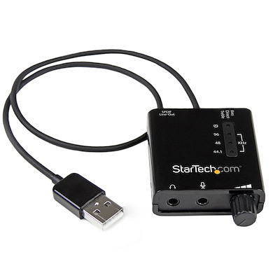
-Startech ICUSBAUDIO2D
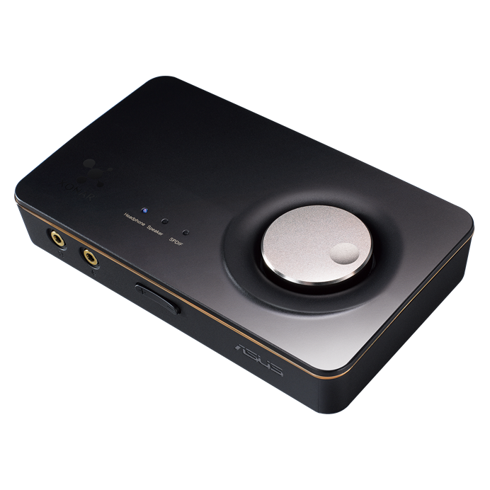
-ASUS XONAR U7 MKII
The Behringer is not so bad but the signal to noise ratio is about -86dBm which is not so good during receive. The noise floor maybe an issue. This device is an entry level so do not expect much
The STARTECH , is 24bits with up to 96khz which is good in theory but in fact this soundcard is bringing some spikes during receive. The signal to noise level is about -95dBm . The transmit and receive quality is better compare with the Behringer
The ASUS XONAR is 24bits up to 192khz sampling. The signal to noise level is about -115dBm . Needless to say this device is a masterpiece for SDR TRX or if you plan to use it with TRX with I/Q output for a panadapter. The transmit and receive quality are cristal clear. In addition this device is providing more setup when using ASIO4ALL Drivers
The soundcard should be connected on the line IN and OUT of the transceiver
When i will have some spare time i will perform a video to show the differences between the device.
The ASUS XONAR is about 80 Euros but it will bring your SDR to another level really!
Final test and tuning
This is a video with the final tuning using the ASUS XONAR U7 MKII Soundcard
Final


i am using 2 relay for the RX and TX sequence , one is for the TX and RX and the other one is for the 2 watts Class A amplifier (power supply 12v)
Just below , the final casing . can be better but since i am not going to compete for a beauty constest with this TRX , it is not so bad


TX & Spectrum check
This check was performed with a TinySA, 20w output from my IRF530 Mosfet amplifier, RF coupler and a 1kw dummy load. The spectrum check was performed prior the Class A 2 wattts amplifier integration.
The following screenshot are demonstrating , the TX output is very clean.


CLASS A amplifier enhancement
The initial check from above measurements were satisfactory but not completely especially for 80 and 40m band, so i had decided to add a Tiny 2W Class A amplifier with associated BPF/LPF controlled by the 74LS145N.
Class-A Power Amplifiers are therefore typically used in applications
requiring low power, high linearity, high gain, broadband operation, or high-frequency
operation.
The absence of harmonics in the amplification process, allows Class-A to be used at
frequencies close to the maximum capability of the transistor.
Class A amplifiers are not the most efficiency for sure therefore in terms of spectral purity and IMD they are far better compare to class AB amplifier.
Since i need only 1 to 2 watts , a class A amplifier will be perfect and i do not need to scratch my head regarding the efficiency. The good thing is with such low power i can use this transmitter fanless.
The amplifier is followed with LPF to ensure a great spectral purity.
Few years ago i bought this tiny amplifier from ebay for my WSPR beacon and this amplifier was really working very well even during long WSPR transmission. This tiny amplifier is able to provide about 1.5w Class A with only few milliwats at the input.


https://www.ebay.fr/itm/174883128392?hash=item28b7d8c448:g:cqsAAOSw7JRhEfno
When i bought it few years ago itwas about 6 or 7 Euros only
Hereafter some figures regarding the amplifier performances.
The measurement was performed with a Nanovna
The following test procedure was used:
1. Turn the amplifiers on to allow them to warm up and guard against turn on transients damaging anything during testing.
2. Turn on the nanoVNA, set the display to CH1/LOGMAG only, 10 dB per DIV, reference position at 5 divisions to be able to see 20 dB gain.
3. Connect a 45 dB attenuator to CH1 and a 6 dB attenuator to CH0 to closely match the expected gain of the preamps under test which is about 20dB
4. Connect attenuators together using a cable. The nanoVNA should be showing a about 20 dB loss over the frequency range which is 80m up to 10m
5. Change to the calibrate menu and select “reset” and then perform a “through” calibration. The new reference should be 0 dB at 5 divisions.
6. Connect the output of the 6 dB attenuator to the input of the amplifier and output of the amplifier to the 45 dB attenuator.
7. Read the amplifier gain in dB directly on the nanoVNA using the marker display.


The SWR is almost perfect from 80m up to 10m with an average of 1.17:1
The amplifier gain is about 18.5dB with an average of 2w from 80m up to 10m
| parameter | Min. | Type | Max. | Unit |
| Frequency | 3.5 | 14 | 29 | MHz |
| Pout CW | 33 | 33 | 33.5 | dBm |
| Power in | 10 | dBm | ||
| Gain | 18 | 20 | 22 | dB |
| Drain Current | 1 | 1.2 | Amps | |
| Supply voltage | 10 | 13.8 | 15 | Volts DC |
| IMD3 2 tone | -34 | -28 | dBc | |
| 2nd harmonic | -30 | -20 | dBc | |
| 3rd harmonic | -30 | -25 | dBc |
Obviously , a LPF filter is mandatory and hereafter the Figures after the LPF filter
Hereafter some figures regarding the amplifier performances after the LPF filter
| parameter | Min. | Type | Max. | Unit |
| Frequency | 3.5 | 14 | 29 | MHz |
| Pout CW | 31 | 32 | 32 | dBm |
| Power in | 10 | dBm | ||
| Gain | 18 | 20 | 22 | dB |
| Drain Current | 1 | 1.2 | Amps | |
| Supply voltage | 10 | 13.8 | 15 | Volts DC |
| IMD3 2 tone | -34 | -28 | dBc | |
| 2nd harmonic | -53 | -50 | dBc | |
| 3rd harmonic | -64 | -60 | dBc |
On upper bands above 14Mhz , the 3rd harmonic is almost null
The integration is pretty much easy and in fact since this amplifier is Class A , it is powerered with 12vdc only during transmit. During receive the amplifier is standing by without any power supply. The very good surprise was according the heat and i do not need any cooling fan.
As mentioned above , the performances provided by this amplifier are really great . The modulation quality is really good and needless to say the spectral quality is compliant with the legal obligation we need to fulfill.
External LPF Control circuit
The LPF is triggered automaticaly by the dedicated LPF Control from the board and a darlington circuit using a UDN2981 or even better an ULN2804 because the logical level at the output of the 74LS145 are inverted. My initial design was using 8 NOT gate transistor design but with the ULN2804, it makes it far easier. The ULN2804 is able to sustain 12vdc up to 500ma .
More details and gerber files are here : https://easyeda.com/F5NPV


You can find some great LPF kit here : https://rv3yf.us/collections/bandpass-filters/products/universal-lowpass-filters-lpf . This LPF is able to handle about 100w
LPF with SWR/PWR and SEQUENCER
https://easyeda.com/F5NPV/ft8qrp-lpf_copy


The output power available after the LPF is about 1.3 up to 1.6w and the current is about 200 up to 300ma.The efficiency is about 50% which is not so bad for a class A amplifier
This LPF is also acting as a RX/TX sequencer and there is one output for the receive path.
Since a Class A amplifier are powered or biased in the “on” state , the amplifier during receive is not powered and the power supply (12volts) is applied only during the transmit.
Hereafter the measurement and results with this amplifier. The measurement were performed with my Mosfet IRF530 amplifier with a power of 30w output on a dummy load with a RF Sampler to feed my TinySa


The results as expected with a Class A amplifier are really good and even exceeding my expectations.
IMD and the modulation envelope are really good also
FINAL INTEGRATION and SPECTRUM
Some pictures of the final integration with the 1w up to 1.5W Class A amplifier. In addition i have integrated a homebrew SWR/PWR bridge and the LPF filter for the Amplifier.
This configuration is providing me about 50w up to 60w with my single 6P45C tube amplifier


The spectrum measument hereafter were performed with my 150w 6P45C tube amplifier with about 100w .


The Spectrum is almost perfect, therefore the fine tuning of the LPF was a bit tedious. The NANO VNA ande TINYSA were very precious tool in order to achieve such result.

SWR/PWR bridge
In order to supervise the integrated amplifier from the front panel , i have integrated a homebrew SWR/PWR bridge


For VD Diodes , i am using BAT41 diodes or 1N5711 . For R1 and R4 since i do not have 50R Resistor , i am using 47R 5w resistor . The Menu is offering to adjust the Resistor Value.
The Toroid core is a ft-80-43 or 140:43 with about 30 turns (The size of your toroid is according the power you are using)
The gerber file for the SWR bridge : https://drive.google.com/file/d/1i1FAbeb4EyGl6EbUAo1TmMHviFV_yVLi/view?usp=sharing
Alternative SWR bridge


The link to download the SWR Bridge Gerber file : https://drive.google.com/file/d/1OKnSJLDMavRQmTEpTh-a3gz-aksZtfnM/view?usp=sharing
The Following was with the IRF530 amplifier testing and SWR / PWR bridge calibration

1 to 3w Amplifier Alternative
This is another alternative for a tiny amplifier as a driver for your QRO amplifier.
The amplifier is about 16 dB. At the output of the amplifier, a 6dB Attenuator is part of the design but can be removed. Taking into account the attenutor, the output power of the amplifier is about +30 dBm (1 watt). Without the attenuator the output power is almost 2.5w but definitly not sure the transistor will sustain it. The operating frequency range of this amplifier reaches 500 MHz. The amplifier usually starts working immediately and does not need to be adjusted. The circuit is also stable when the supply voltage is unchanged. Alternatively you can use a 2N3866 which is almost equivalent . With a 2N3866 the output power is a bit higher with about 3 to 4w without the attenuator. The best is to use a transistor socket and you can swap the transistor with ease
My second TRX is equipped with this amplifier. You can remove the 6db attenuator a the output (My final amplifier need only less than 1w)


The gerber file :
10w Amplifier (Ongoing testing)
This design is not finalized yet and i am still testing it. With 13.8vdc this amplifier is able to provide up to 10w . This tiny amplifier is using a 2N5109 as a driver and a IRF510 or IRF530 (i am still testing both mosfet) for the final. This amplifier should be followed with a LPF filter.
All details : https://easyeda.com/F5NPV/5w_rf_amplifier_irf510


With 50mw input from the SDR , i can have from 5w up to 10w output. this level can be adjusted with the variable Resistor (Driver).
The 2N5109 driver working range is from about 0.5 to more than 30 MHZ with 16 dB of stable gain and very good linearity. It can produce +15dBm up to +30dBm of output power, while still in linear operation.
The IRF530 biasing is about 3.7vdc and 20ma.
J1 : the main purpose is in case of current sensor integration or if you prefer to use a separate power supply with current limiting capabilities.
T2 Transformer: you can use a FT50 or FT37-43
For this transformer the wire should be twisted. During the winding you need to identify 2 pairs :
-Pair identify with 4 and 3 is the primary
-Pair identify with 1 and 2 the secondary
The link for 2 and 4 is on the PCB and you just need to solder the 4 identified pins on the PCB. This transformer is providing a 1:4 ratio
For T1 transformer it is pretty much the same principle and the main difference is regarding the number of turns which is 10.


Obviously the IRF530 should use a heatsink .
i will put the Gerber files when all tests will be done
FANLESS PC
For PowerSDR i am using an industrial FANLESS PC with a dualboot (Ubuntu + Windows 10). The computer is located underneath the table. I am using a wireless Mouse + Keyboard

BOM
| Component Name | Designation | Qty | note |
| ARDUINO NANO V3 | ARDUINO NANO V3 | 1 | |
| 105 | C1,C2,C15,C16,C17,C18 | 6 | multilayer |
| 221 | C13,C14 | 2 | ceramic |
| 10uF | C19,C20 | 2 | elco |
| 223 | C21,C22,C23,C24 | 4 | ceramic |
| 221 | C25,C26 | 2 | ceramic |
| 100uF | C28,C30,C35,C77,C93,C94,C96 | 7 | elco |
| 10uF | C29 | 1 | elco |
| 104 | C3,C4,C31,C36,C37,C38,C40,C39,C89,C90,C91,C92,C95,C97,C98, C99,C100,C41,C42,C43,C44,C45,C46,C72,C73,C74,C75,C76 | 28 | ceramic |
| 10uF | C33,C34 | 2 | elco |
| 102 | C47,C48,C49,C50,C52,C53,C54,C55,C60 | 9 | ceramic |
| 10uF | C5,C6,C7,C8 | 4 | elco |
| 201 | C51 | 1 | ceramic |
| 561 | C56,C57,C59 | 3 | ceramic |
| 121 | C58,C70 | 2 | ceramic |
| 471 | C61,C65 | 2 | ceramic |
| 361 | C62,C64 | 2 | ceramic |
| 391 | C63,C66,C68 | 3 | ceramic |
| 181 | C67 | 1 | ceramic |
| 271 | C69,C71 | 2 | ceramic |
| 223 | C9,C10,C11,C12 | 4 | ceramic |
| 1N4148 | D1,D2,D3,D10,D9,D13,D14,D15,D16,D17 | 10 | |
| 5V6 | D11,D12 | 2 | zener |
| TL084P | IC1 | 1 | |
| NE5532N | IC2 | 1 | |
| 74HC4051 | IC3 (Be carefull with fake one) | 1 | |
| AMS1117 5.0V | IC4 | 1 | smd |
| 74AC74N | IC5 (Be carefull with fake one) | 1 | |
| 74LS145N | IC6 | 1 | |
| AMS1117 3V3 | IC7 | 1 | smd |
| 7809 | IC8 | 1 | |
| PINHD-1X3 | JP1 | 1 | DC IN |
| encoder dial | JP2 | 1 | |
| SWR | JP3 | 1 | header |
| PTT IN | JP4 | 1 | molex |
| to LPF | JP5 | 1 | header |
| TX OUT | JP6 | 1 | molex |
| RX IN | JP7 | 1 | molex |
| LCD 16X2 | JP8 | 1 | |
| Relay 12v | K1,K2,K3,K4,K5,K6,K7,K8,K10,K9 | 10 | 8 pin |
| 100uH | L1,L2,L19 | 3 | |
| 1uH | L10,L12,L14 | 3 | |
| 0.47uH | L13,L15,L17 | 3 | |
| 0.22uH | L16,L18 | 2 | |
| 47uH | L3 | 1 | |
| 4.7uH | L4,L6,L8 | 3 | |
| 10uH | L5 | 1 | |
| 2.2uH | L7,L9,L11 | 3 | |
| TX | LED1 | 1 | RED |
| RX | LED2 | 1 | GREEN |
| CAT | LED3 | 1 | YELLOW |
| BS170 / 2N7000 | Q1 | 1 | |
| 27 / 25MHz | Q2 | 1 | |
| 2N3904 | Q3,Q4,Q5,Q6 | 4 | npn |
| 2N3906 | Q7 | 1 | pnp |
| 2K2 | R1,R2,R28 | 3 | |
| 100 | R13,R63 | 2 | |
| 1K | R17,R18,R19,R20,R27,R32,R31,R43,R44,R49,R50,R51,R52,R53,R 54,R69,R41,R42,R61 | 19 | |
| 68 | R29,R30 | 2 | |
| 10K | R3,R4,R5,R6,R7,R8,R15,R16,R21,R22,R23,R24,R26 | 13 | |
| 220 | R34 | 1 | |
| 560 | R35 | 1 | |
| 6R8 | R36 | 1 | |
| 33 | R37,R39 | 2 | |
| 390 | R40 | 1 | |
| 15K | R45,R46,R58,R60 | 4 | |
| 02/02/21 | R47 | 1 | |
| 10K trimpot | R48 | 1 | multi turn |
| 4K7 | R55,R56,R57 | 3 | |
| 150 | R59,R70 | 2 | |
| 470 | R62 | 1 | |
| 10 | R64 | 1 | |
| 100 trimpot | R65 | 1 | multi turn |
| 240 | R66 | 1 | |
| 62 | R67,R68 | 2 | |
| 330 | R9,R10,R11,R12,R25,R33,R38 | 7 | |
| SET | S2 | 1 | tach sw |
| Si5351A | U1 (Be carefull with fake one) | 1 | |
| PHONE | X10 | 1 | audio jack |
| LINE OUT | X11 | 1 | audio jack |
| MIC | X8 | 1 | audio jack |
| LINE IN | X9 | 1 | audio jack |
| Pin Header | male + Female | 1 |
All ICs (except the SN74AC74 and SI5351) , transistor ,resistor and capacitor are from MOUSER
The relays , the arduino nano, the inductance and many more are from Aliexpress:
Arduino Nano : https://fr.aliexpress.com/item/4000036402472.html?spm=a2g0s.9042311.0.0.7ec56c37Fsgs7j
The inductance : https://fr.aliexpress.com/item/4000709985793.html?spm=a2g0s.9042311.0.0.7ec56c37Fsgs7j
The SN74AC74 : https://fr.aliexpress.com/item/4000115726569.html?spm=a2g0s.9042311.0.0.27426c37fk9sRW
The SI5351 : https://fr.aliexpress.com/item/32906315061.html?spm=a2g0s.9042311.0.0.27426c37XhiEbn
The audio connectors : https://fr.aliexpress.com/item/32694891007.html?spm=a2g0s.9042311.0.0.27426c37Y4ECwk
The relays : https://fr.aliexpress.com/item/32656965533.html?spm=a2g0s.9042311.0.0.27426c37x8GXyn
Download
For the download because of WordPress restriction the files are with *.doc extension . Nevermind it is in fact a zip file and you can extract the file using your favorite winzip or any other archiver software.
Special release for PowerSDR you can use : https://drive.google.com/file/d/13RvNX7iPxzgHR3kxQk0YyhJ7pMIW5mMo/view?usp=sharing
Arduino Nano V6 hex file :
https://drive.google.com/file/d/1phx2hHXN3ZEg8itbpfaa1rRcNI_zXIEN/view?usp=sharing
Gerber Files:
https://drive.google.com/file/d/15bJM71A4pfZqxM-sm_Mbsj1eakzSLGMM/view?usp=sharing
BOM :
https://drive.google.com/file/d/1KkTR9BTD5XPy3ph2_YG5D54OhG7Ay-50/view?usp=sharing
Multiple PowerSDR release for homebrew SDR:
https://powersdr.mis.ks.ua/download.html
you need to download :
PowerSDR 2.8.0.187.1 X64 – Modified LPT driver 64bit
or
PowerSDR 2.8.0.187.1 X86 – Modified LPT driver 32bit
PowerSDR Setup
First you need to download the following PowerSDR software. This Software was initially compiled for the SDR-1000 TRX which was using the LPT port . For our TRX you do not need the LPT port (Must be setup to zero ”0″) and all is controlled by the CAT connected directly to the Arduino Nano.
http://cloud.mis.ks.ua/index.php/s/YQGJrcLMGT2WKrB
Then the setup is pretty much straight forward and you just need to to setup according the hereafter screenshots:
It is mandatory to setup the LPT address to 0 (zero)

Then you need to setup your CAT control

Soundcard setup using the Asus XONAR , you will to adjust this setting according the soundcard you are using.

When opening PowerSDR you will need to create your Transceiver setup
Add your transceiver TRX

Then just follow the following screenshots

CAT and VAC configuration

For virtual channels VAC i am using com0com

Transceiver Calibration
The SI5351 needs to be calibrated . Inorder to achieve this task you will use the dedicated menu provided by the arduino firmware and PowerSDR
You will need to tune your VFO for example on 10Mhz (DSB mode) and press the S2 to access the calibration Menu (CorRef)
The red vertical line should be in the middle of the 10Mhz reference signal peak.

If you are using a rotary encoder which include a swith you can wire S2 on it

The CorRef Menu : you just use the rotary encoder to change the Reference value. When done you just need to press the reset on the Arduino nano to save the value.
Hereafter a quick video to explain the calibration process which is very simple:
CW
For CW you can use this simple circuit


The following setup should be applied to PowerSDR and it will be according your COM where your adapter is detected by Windows . Mine is COM1

You will need to adjust the signal shapping according your preferences.
For automatic call you can use the CWX features

If you are Not comfortable with this circuit you can instead use a FTDI RS232 Adapter

This solution is working also very well. The PowerSDR settings are identical compare to the previous circuit.
Final and presentation
Summarize
First of all , i really need to thanks a lot :
-YE3CIF, Arif from Indonesia . A great designer and homebuilder. You can find now the PCBWAY project compiled by him : https://www.pcbway.com/project/shareproject/SDR_Transceiver_10_160_meter_band.html (36 USD only for 5 PCBs, so it is about 7.5 Euros only for one PCB)
-UT3MK Shadrin Yuri from Ukraine for all information provided and thanks to his wonderful forum (https://ut3mk.at.ua/) where i can find all the information i need and especially for the Arduino Firmware.
Building this kind of transceiver is providing the oportunity to put your hand into the SDR technology which is definitly great. The simplicity of this kind of design is simply astonishing regarding the results and performances provided. This kind of transceiver is not a DUC/DDC transceiver and basically mostly dedicated as a base station.
Since this TRX design is simple , the key is to use :
-A good sound card and i recommand the ASUS XONAR MKII which is a blast in terms of performance. The Startech ICUSBAUDIO2D is providing decent results
-Genuine component especially for the SI5351 , 74AC74 and the CD4051 : This is mandatory for this transceiver.
The only difficulty is the soldering of the SI5351 , for other components they are THD standard one.
You don’t need to be an expert in either to build or operate a SDR
• Most of the “Digital” is in the computer/sound card
• All of the ”DSP” is in the computer software/firmware
• With SDRs, low cost does not mean poor performance at all
Since this tiny transceiver is really performing well , it is now my station main transmitter and use it daily without any issue so far.

Bonjour
Je compte monter ce transceiver, mais j’ai le choix de faire 5 PCB dont 4 qui seront inutiles ou alors me procurer le Kit sur le site russe http://radio-kits.ucoz.ru/. Ce kit est en CMS et je préférerai votre solution. Auriez-vous un PCB à me vendre ? Merci pour votre réponse et encore félicitations pour cette réalisation accompagnée de précieux conseils et très détaillée.
73 QRO Gilles F1BFU
LikeLike
Bonjour Gilles,
Je suis vraiment désolé mais je n’avais que 2 PCB (J’ai monté deux TRX) car nous avions partagé avec d’autres OM (30 PCB au total) une commande groupée . L’idéal serait que d’autres OMs soient intéressés afin de pouvoir passer une commande groupée.En passant peut etre par un forum tu pourrais peut-etre lancer l’idée.
Pour le reste pas évident de detailler une construction , car on ne sait jamais ou placer le curseur. Concernant la construction , on peut difficilement faire plus simple . Le LPF fut la partie la plus chiante , le résultat final permet de s’affranchir de tores a bobiner et l’utilisation de valeurs standard pour les selfs permet de simplifier tout cela. Le circuit imprimer est la 3eme itération et ne devrait plus bouger maintenant. (Les deux premiéres cartes comportaient de petites erreurs et n’incluait pas la gestion des LPF (interne et externe).
Bonne construction 73s QRO Didier
LikeLike
Bonjour Didier
Je viens de recevoir mes PCB (5) pour cette réalisation. Je vais donc attaquer la soudure. Les CMS en premier. Je vous tiens au courant. Bien noté : “Composant d’origine spécialement pour le SI5351 , 74AC74 et le CD4051”. Le conseil est très important. Pour le quartz j’ai des 27mHz. Avez-vous mis le Nano R3 sur un support ?
73 QRO Didier
Gilles F1BFU
LikeLike
Didier : pour le Nano R3 je vois bien les supports donc pas de problème. Pour l’encodeur rotatif j’ai des encodeurs avec bouton poussoir donc pas besoin de switch SET. 73 QRO Gilles F1BFU
LikeLike
salut Gilles, oui le Nano est sur un support. Sur mon deuxieme TRX j’ai mis egalement tous les relais sur des supports. Concernant le CI , clairement il faut du original bien que mes 74AC74 tout comme les SI5351 viennent de chez aliexpress lol… J’ai preféré le préciser au cas ou car chez aliexpress c’est un peu la loterie. Je vais mettre en telechargement le dernier firmware dans la soirée. Si tu ne te plantes pas dans les soudures et valeurs des composants , clairement ce TRX tombe en marche . J’ai controlé pour la forme les filtres du LPF et ils ont OK avec les valeurs indiquées. Concernant l’encodeur oui c’est ce qu’il faut faire. Je te conseille de cabler le reset de l’arduino qui sert pour la calibration. J’ai mis un bouton poussoir sur l’arriére sachant que normalement la calibration ne bouge pas . J’ai mis une vidéo en ligne pour une methodologie simple pour la calibration , si par contre tu as un fréquencemetre precis tu peux faire la mesure directement sur CLK0 (tu multiplies par 4 la frequence). Bon montage
73S Didier
LikeLike
Dans la section download , j’ai mis le dernier fichier qui a été crée par Yuri specialement pour ce TRX . Les autres firmware utilisent toutes les sorties CLK et comme nous n’en avons pas besoin, cela permet d’avoir une seule sortie et ainsi le verrouillage de la PLL génére beaucoup moins de bruit et pas de sorties qui n’etainet chargées par aucun circuit.
LikeLike
Hi Didier,
This looks like a very nice project to build in the coming winter months.
Just two questions:
1) do you have a spare PCB, or do you know anyone who has one, that I can obtain for a fair price? With the new tax rules in the EU, the price for ordering them from PCBway may be a bit too high.
2) In my shack every computer runs Linux. Do you have any experience using Linux SDR programs with this TRX, and if so, what software would you recommend?
Thanks and 73
Hans, PA3CRZ
LikeLike
Hello Hans ,
Unfortunately i do not have spare anymore but you can contact maybe Gilles F1BFU, you can find some post from him and he ordered few PCB maybe he has one in spare.
The TRX works only with POWERSDR and Expert SDR and so far i cannot found any program running with Linux .
LikeLike
Very interesting SDR project, do they publish the source for the nano firmware, is there a link for that ? Thanks?!!
LikeLiked by 1 person
Hello , unfortunately no they do not publish the source code .
This transceiver is working really well and use it as my main transceiver. Simple , easy and very cheap. SDR technology is really great and with some very common components you can achieve a very decent TRX
73s Didier
LikeLike
Hi, please give details of connecting isolation transformer between TRX and PC.
I made this SDR,working fine for me.But I have a problem with the sound card due to regular RFI issues.
LikeLike
Hello ,the insulation transformer is using LINE IN and LINE OUT. But it will depend how serious is your RFI . You need also to add ferrite or toroid on your different wires (Audio , USB) . My recommandation is to sort out your RFI issue with a choke balun on your antenna . I am using one and please refer to this page : https://f5npv.wordpress.com/endfed-cmc/
73s Didier
LikeLike
Bonsoir Didier
Bravo deja pour le contenu de votre site.
Pour le LMR SDR j’ai telechargé la V6.hex
ce firmware gere t-il les deux freq de ref du si ou il faut mettre absolument un 37 par exemple?
merci
Seb F4HFK
LikeLike
27 pas 37 dsl
seb
LikeLike
Salut,
ce Firmware gere le 25 ou 27 mhz au choix
LikeLike
Bonjour Didier
C’est un parametre du programme arduino je suppose
merci
73s Seb F4HFK
LikeLike
Bonjour,
Il s’agit d’un paramètre que tu peux ajuster dans le menu de configuration de l’affichage LCD . Tu pourras choisir la fréquence souhaitée qui va de 25Mhz jusqu’a 27Mhz . Pour sauvegarder il faut faire un reset de l’arduino Nano. Ce menu sert également pour la calibration du coupe Arduino/SI5351, tu peux choisir et modifier également une vitesse pour le port Serie etc etc …. .
73s Didier
LikeLike
Didier re
Merci pour ces précisions. Dès que j’aurai fini l’implantation des composants et fait mon premier démarrage je me focaliserai sur ce point. j’ai acheté un QH40A pour avoir une température fixe de 40° sur le quartz de 25 ou 27.
Merci
Seb F4HFK 73s
LikeLike
Hi Didier, maybe you can help clarify the following for me as the silkscreen is a bit messy around the 40m relay. From the schematic it seems that top tow of capacitor should both be 361 with bottom row (closest to relay) should both be 471. The silkscreen on the pcb doesn’t look correct here as it has them reversed.
LikeLike
Hello Peter,
i will try my best since i cannot join a picture in the comments:
One the top of relay just below the 1uh inductor from left to right : 471 – 361
on the top of the relay just below the row of capacitor from left to right : 361 – 471
i use a lot the 40m band and these value are correct.
i agree it is not so clear since lack of space to include the labelling
hope it helps
73s Didier
LikeLike
Thanks Didier, that helps clarify that for me! I have another question/issue I would like your brief thoughts on. I believe the CD4051’s I nought may well be fake. I have confirmed 5v by measuring pins 8 and 16 on the chip, the clock input is correct on pins 11 and 10 from the 5351 (using scope), the 3Mhz RF signal I am injecting can be seen on pin 3, however using the scope I do not see any useful signal on pins 1,2,4,5, even checking pins 2 and 13 on the TL084 confirms no useful signal. I have ordered replacements from digikey as they have to be authentic but is there anything else I should check in the interim ? Thanks!
LikeLike
Hello Peter,
As far i remember my CD4051’s are from Mouser , Since the 5vdc, input clocks or signal from 74AC74 are OK you should have output from the CD4051. This part is really straight forward.
73s Didier
LikeLike
Hi Didier!
I have SI5351A-B02075GT, but it has a hex address 0X6F, please let me know if it will work with your soft.
Regards, Bogdan SP7GRV.
LikeLike
Hello, currently the firmware is compiled with a SI5351 Standard library using 0x60 I2C address
LikeLike
Hello,
i have a SI5351A in spare with 0x60 address . Just drop me an email with your address using the contact webpage and i will send you the chip.
73s Didier
LikeLike
Hello Didier! I just assembled all the components on the PCB and ran SDR tests.
The plugs are very positive on almost all bands, I checked the receiving and transmitting part on the mixer itself, I still have to refine the input filters and make the amplifier – driver and, of course, the housing. but overall I am satisfied with the work of the SDR.
When I finish SDR, I take care of FT8QRP AFP / FSK TRX, I have already tried it on the test board, FT8 receives and transmits.
Yours sincerely, Bogdan SP7GRV
LikeLike
Hello Bogdan,
Great News , you will see this transceiver with you minor adjustment will perform great i am sure . For mine and i guess with a bit luck was perfect and i didn’t need any adjutment on the filter. The critical part i will say is regarding the audio cable you will use and you will probably need to wrap them with few turn with high permeability toroid core. The Arduino connexion to the computer it is recommended to disable the power from the computer because in fact we do not need it since the Arduino is powered from the main board.
73s Didier
LikeLike
Hello, Didier. The 2N3904 works well at 30MHz? The amplifier gain is flat from 3 to 30MHz using this transistor? 73 de PU2MBZ.
LikeLike
Hello ,
The 2N3904 is providing me about 45mw at 30mHz , for for lower frequencies i am above 50mw
73s Didier
LikeLike
Hi, instead of using 2N5109 or 2N3866, it’s possible to use BFW16A? 73 de PU2MBZ.
LikeLike
Hello
What does R MIC mean in PCB picture.
Anton, S55TA.
LikeLike
Hello Anton
This is a resistor you may need to adjust according your microphone input . For me i did not need to adjust it
73s Didier
LikeLike
Hello, Is it available with Si570 or only Si5351?
Is it possible to measure SWR in software with this version or only in hardware?
73
YU1OTW
LikeLike
On the PCB you can find a 3 pin connector for a SWR/PWR coupler . The SWR/PWR cannot be measured only with Software . You need also SWR/PWR coupler. The couoler can be connected with an output amplifier
LikeLike
Hellooo sir from Cuba, I am CO4XT. Is it posible to implement the dds using it in quadrature Outputs from si5351? I think Would be an gerat option to take in count for the next version. This link from wa5bdu can be usefull. Thanks in advanced. 73 from el81nt.
http://www.wa5bdu.com/si5351a-quadrature- herramientas vfo/&ved=2ahUKEwit_Nah58X7AhVLRDABHasjCjcQFnoECA4QAQ&usg=AOvVaw0yB9e6sag_2OE53UBF-5ZG
LikeLike
Hello,
Many option are available and the one proposed can implemented therefore you will need to add in the code the CAT Control , PowerSDR Control and misc likely the preamp control.
73s Didier
LikeLike
Hi,
Have you noticed any carrier leakage issues with this SDR?
LikeLike
Hello,
At least no particular issue regarding the carrier
73s Didier
LikeLike
Hi i am here to thank you for the information u have shared .. and the way u presented is Easly understandable. i have a request if u have .ino file of this arduino hex file, plz share it with me if possible
73
LikeLike
Hello,
Unfortunately the source code was coming initially from UT3MK but for different reasons not be be disclosed .
73s Didier
LikeLike
Understand Thankyou
LikeLike
Hi,Since I can’t find an option to uplod image,I had sent you an email.Please check it.
LikeLike
Hello,
But you cannot upload image on my website you must have admin right to do that. What can of image you want to upload
LikeLike
Hallo Didier “I am here to thank you for the information u have shared”
I am an real old man(OM 80 this year, but still active in DIY I experimenting with SDR an looking for the SOURCE-CODE controlling “ARDUINO-NONO” – PWRSDR
So i need Your help …. wher can I get this “SOUIRCE-CODE” to implement my own modifications.
LCD-Display 4×20; changed Bandselection, …..
I hope you can support me …. thank in advance
vy 73 de DJ8UZ Hermann
LikeLike
Hello Herman,
The source code is currently not available and since the orignal one is from UT3MK and YE3CIF proprietary cannot be disclosed. Likely some other projects it is not suitable to avoid to find later copycat products on Aliexpress.
73s Didier
LikeLike
Hi. I’m trying to build your lpf scheme( with built in swr/pwr).
But i can’t find witch coils i need to use for swr analyzer,and how many turns i need to make.
can u clarify this please?
LikeLike
Hello,
you can use a FT80-43 toroid and with about 25 up to 30 turns
73s
Didier
LikeLike
Thank u for anwser, Didier. And thank u for great project.
LikeLike
First of all – Welcome! Secondly, fantastic project, circuit boards for me and several colleagues already in production. Thank you very much for sharing your and the whole team’s great work. I have a few questions (I ran “dry” the Arduino related part). Do you recommend any fuse bits when uploading the firmware? Or is it irrelevant?
Secondly, I can’t get PowerSDR-2.8.0.187.1-NOLPT to work stably – settings as recommended LPT 0 and the right CAT port – I feel like it oscillates between RX and TX and crashes. On the other hand, PowerSDR-2.8.0.163.1-NOLPT version seems to be much more stable, works generator control frequency does not quite match but it’s a calibration issue I guess – of course I know about rx/tx offset. I will investigate further – for now I have not connected the display 😉 so I can’t do calibration – time will come for that.
I’ve noticed that in this PowerSdr I can’t reach the end of the 10m band – the SI goes out at about 29,300 which is roughly 117MHz – interestingly this piece works up to 200MHz controlled by another script without any problems. Crystal frq. not set properly? We will see 😉
Additional question about SI5351A – in finished circuit it is powered by 3.3V from Vreg – it is clear but is it safe for it to work with 5.0V logic from NANO? – there is no level converter there – unless there is some other trick I don’t know about 😉
Thanks again – all the best!
LikeLike
Hello,
For the Arduino NANO if it is already pre-loader and the bootloader is already installed , there is no need to setup FUSE. i am using XLOADER to upload the HEX file.
According PowerSDR-2.8.0.187.1-NOLPT to be honest i have no idea since i am using also this release and working great and cannot undertand why it is swinging from TX to RX since this is a CAT command to trigger this status but you can try to enable or disable ”allow kenwood AI Command” in the CAT setup. Yes later on you will need to perform a calibration . for the limitation on 10m you will need to perform 2 things : First to ensure the PLL is setup to 900Mhz but unfortunately you will need the LCD screen and there is a dedicated menu for that, second to ensure in general , hardware configuration in the DDS you need to activate ”expert” and then put 9000,0 in the IF (Hz) and 1 in the PLL Multiplier.
For the SI5351 the core VDD is 2.5V or 3.3V and not 5V, so it is normal the regulator is feeding the chip 3.3V
Good luck for your build. This TRX is for 3 years my main TRX and really working well.
73s
Didier
LikeLike
Hello!
I managed to assemble and get the board working 😉
So I have a few more questions if you would be so kind to help me with a few things I would be extremely grateful, I’m in love with this project and I think it is worth it to get it to a working TRX (I even bought an Xonar because my Focusrite 18i8 is completely unsuitable – very difficult signal routing) The receiver works fine, the transmitter generates a good signal. I have a problem with the receive and transmit frequencies.
How I did the calibration I will describe how – while transmitting I watched the signal from the SI generator and set it with the help of correction in the menu – exactly to the frequency equal to 4x the PowerSdr operating frequency (correction value about 181000). In this way, watching the signal on the second SDR – I have transmitting exactly where the PowerSdr is set. The problem is with the receiver. I have a very accurate 10MHz generator and its signal is received in Power Sdr about 1.3 kHz below frequency. Doing the calibration the other way – as you show in video – calibrating on the receive side I have to correct to a value of about 444000 in the menu to receive this reference signal on the 10MhZ on PowerSDR. But there is a problem – then the transmit frequency is shifted relative to that displayed in PowerSDR. I watch what’s happening with the SI generator and I can see the shift
of VFO signal between transmit and receive – but that’s how it’s supposed to be from what you write. The problem is that already from the point of view of the finnaly transmitted/received signal – I have a shift that worries me. I don’t know what this inconsistency is due to?
The quartz resonator is 27.0 MHz – so that’s exactly what the menu says. The intermediate frequency is set to 9000 in PowerSDR. I have no idea how to remedy this offset….
One more thing – you write on the site that the firmware is V6 and that’s the name of the file – but on the display it reports as V4 – is that ok?
Another thing – the transistor in the preamp is heating up a lot – and when I turn on any mode where it is in the signal path it becomes a terrible mess (on the waterfall) – I have the impression that it completely clogs up everything – and I have antennas that are practically not super effective…. So signals are rather weak. Is it possible that the preamp goes into oscillation? How can I most simply check and remedy this?
PS. I have found 74ac74n working at 24MHz band – ist ok 😉
But for 28 megs I still have problems with VFO so I cant check it. The SI chip itself, as soldered in board, can go up to 150MHz like a charm (I use sample program in Arduino using assembled transciever board to be sure) and if using transciever firmware it is not working properly at 10m -cannot see VFO signal, it drops out at about 100Mhz…
I am very much asking for help – thank you and best wishes.
Gregory SQ3DLA
LikeLike
Hello Gregory
I will try my best according all your questions to provide as i can a response;
1) According the frequency shift and offset during RX , since i never had this issue i am highly suspecting a setup on POWERSDR and please check in the setup –> Option , the Spur reduction shall be unchecked
2)for the peamp Transistor , same i do not have this issue and the maybe check the components regarding the gain control of this transistor , may be changing some components value (In particular R36,R37 and C46) may help but honestly i need to dig on it since nobody has reported this issue.
3) The 74AC74 can be an issue . i had the same issue with a 74AC74 from Mouser and replace it with a chip from Aliexpress. you need also to ensure the PLL is setup on 900Mhz from the LCD Menu. The intial PLL SETUP from the firmware is 700Mhz which is not sufficient for 10m. To achieve the Phase Shift you really need to setup the PLL to 900Mhz
i will check this coming week end regarding the preamp issue and will need to open my transceiver to perform some measurement before.
Best 73s
Didier
LikeLike
Thank You!!!
Yes it was the issue!
All The Best!
G.
LikeLike
Spur reduction when enabled shifts reciever “software way” 😉
LikeLike
hi again. i’m trying to build lpfs for all my family.
and i have a problem. my pcb is shorted. i already solided relay and capacitors, and unable to check fresh board by myself.
i use hk4100f-dc12v-shg relay, and as i see in docs it’s the same, but i’m not sure. it shorts between ground and 12 volts. also i have short between bottom relay outputs. it’s shown at screenshot. and i have the same problem with all of may boards. in the same places.
could you help me please?
is it possible that the problem in pcb? or maybe it’s my relay problem? or maybe u had a similar problem?
LikeLike
i found an error. https://easyeda.com/F5NPV/ft8qrp-lpf_copy there is c24 and c32 capacitors moved from it’s initial position. and becouse of that pcb is shorted. fix it please.
btw, i was really scared when your site was blocked by TOS. maybe you need to use self hosted domain instead of wordpress as service
LikeLike